

Typical Connection Example
Caution about Cabling
-
Be sure that the power is off before plugging or unplugging connectors.
-
Pay attention to straight insertion and removal of connectors by holding the connector's body.
-
Be sure there is no stress on connectors.
-
Be sure not to pull cables hard or hang CM3 by holding cables. It may result in damaging connectors.
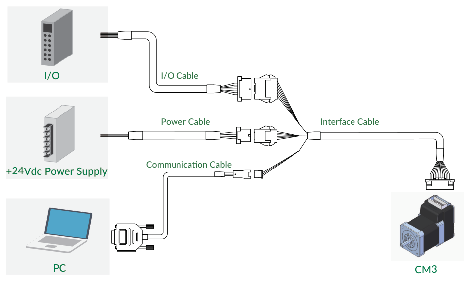
The typical connection differs by control type as follows.
Pulse Type
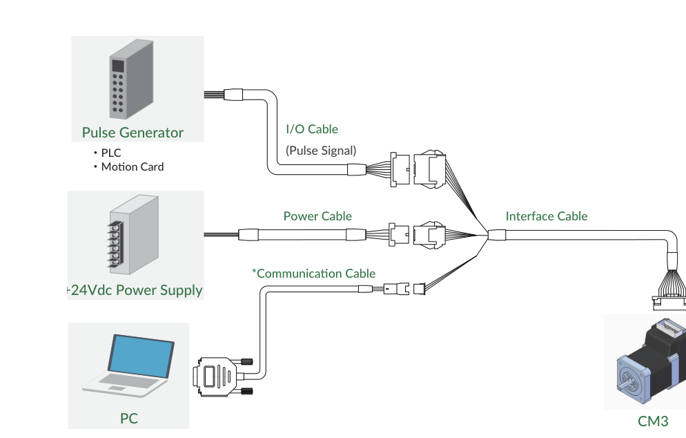
* The communication cable is required when changing the CM3 settings from a PC.
I/O Type
Direct Type
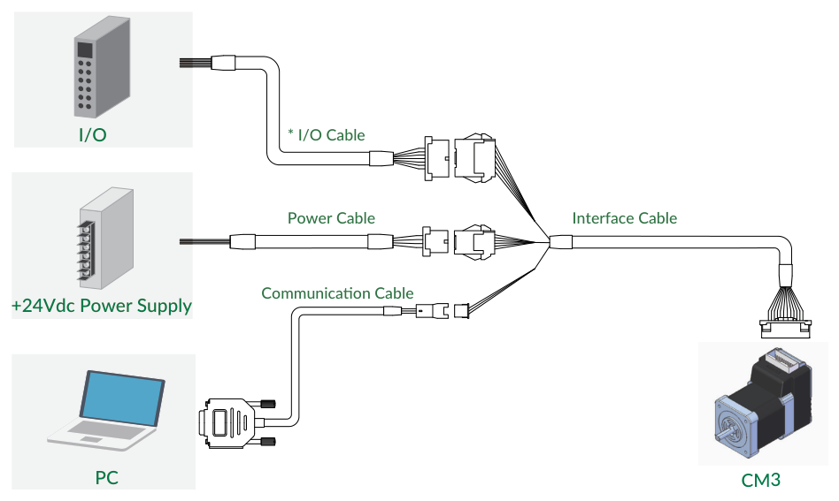
* The I/O cable is required when the I/O (input/output) function is used in addition to command control from the host.
Connector Pin Layout and Functions
Pin layout and functions of CM3 cables are described below.
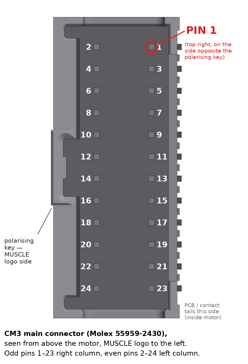
Main Connector
CM3 has a 24-pin connector on the top. The pin layout, names and functions are as follows. The functions of IN1 to IN6 depend on the selected control type.
|
No. |
Name |
Pulse Type Function |
I/O Type Function |
Direct Type Function |
|---|---|---|---|---|
|
1 |
FG |
Frame Ground |
Frame Ground |
Frame Ground |
|
2 |
D_GND |
Digital Ground |
Digital Ground |
Digital Ground |
|
3 |
D_GND |
Digital Ground |
Digital Ground |
Digital Ground |
|
4 |
ALARM |
Alarm Output |
Alarm Output |
Alarm Output |
|
5 |
RXD0 |
RS232C Receive Data |
RS232C Receive Data |
RS232C Receive Data |
|
6 |
OUT3 |
Output 3 / Z-phase |
Output 3 / Z-phase |
Output 3 / Z-phase |
|
7 |
TXD0 |
RS232C Transmit Data |
RS232C Transmit Data |
RS232C Transmit Data |
|
8 |
OUT2 |
Output 2 / B-phase |
Output 2 / B-phase |
Output 2 / B-phase |
|
9 |
STO_IN- |
STO Input - |
STO Input - |
STO Input - |
|
10 |
OUT1 |
Output 1 / A-phase |
Output 1 / A-phase |
Output 1 / A-phase |
|
11 |
IN6+ |
CW / Step / B-Phase Pulse + |
Start・Stop |
CW Inching・Jog |
|
12 |
STO_IN+ |
STO Input + |
STO Input + |
STO Input + |
|
13 |
IN5+ |
CCW / Dir / A-Phase Pulse + |
Limit Sensor |
CCW Inching・Jog |
|
14 |
IN6- |
CW / Step / B-Phase Pulse - |
Start・Stop |
CW Inching・Jog |
|
15 |
IN_COM |
IN1 to 4 Common |
IN1 to 4 Common |
IN1 to 4 Common |
|
16 |
IN5- |
CCW / Dir / A-Phase Pulse - |
Limit Sensor |
CCW Inching・Jog |
|
17 |
IN3 |
Servo on/off |
Select Motion Data |
Servo on/off |
|
18 |
IN4 |
Torque Limit |
Select Motion Data |
Manual Mode |
|
19 |
IN1 |
CCW Limit Sensor |
Origin/Limit Sensor |
Origin/Limit Sensor |
|
20 |
IN2 |
CW Limit Sensor |
Select Motion Data |
Limit Sensor |
|
21 |
P-GND |
Power Ground |
Power Ground |
Power Ground |
|
22 |
P-GND |
Power Ground |
Power Ground |
Power Ground |
|
23 |
POWER |
+24Vdc |
+24Vdc |
+24Vdc |
|
24 |
POWER |
+24Vdc |
+24Vdc |
+24Vdc |
Connector: 55959-2430 (Molex)
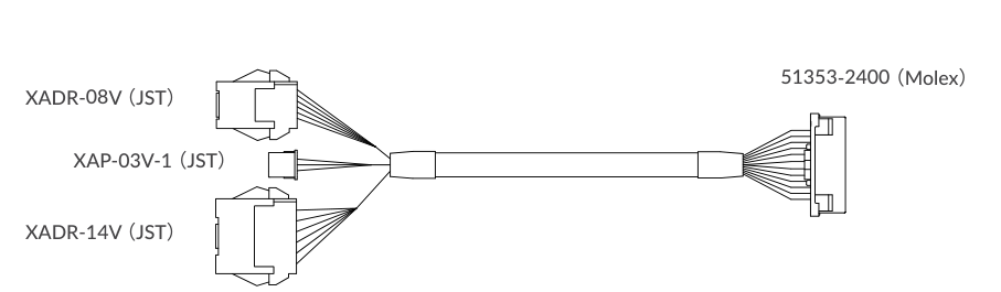
Interface Cable A (400mm, 1000mm, 2000mm, 3000mm, 5000mm)
Product Number: CMIFA1-****WR (****: Cable Length)
-
Wires: 01 - 20 pin … AWG26 UL20276 (80℃ / 30V)
-
Wires: 21 - 24 pin … AWG24 UL20276 (80℃ / 30V)
Communication Cable A (1000mm, 2000mm, 3000mm, 5000mm)
Product Number: CMRSA1-****W (****: Cable Length)
-
Wires: AWG26 UL1007 (80℃ / 300V)

PC side
|
Color |
No. |
Name |
Function |
|---|---|---|---|
|
GRY |
2 |
RXD |
RS232C Transmit Data from PC |
|
ORG |
3 |
TXD |
RS232C Receive Data from PC |
|
WHT |
5 |
D_GND |
Digital Ground |
CM3 side
|
Color |
No. |
Name |
Function |
|---|---|---|---|
|
ORG |
1 |
RXD |
RS232C Receive Data from CM3 |
|
GRY |
2 |
TXD |
RS232C Transmit Data from CM3 |
|
WHT |
3 |
D_GND |
Digital Ground |
I/O Cable A (1000mm, 3000mm, 5000mm)
Product Number: CMIOA1-****S (****: Cable Length)
-
Wires: AWG28 UL758 Style2464 (80℃ / 300V)
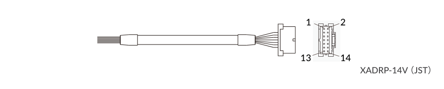
The color of the wires is one of the two tables below. The functions of IN1 to IN6 depend on the selected control type — see the Main Connector pin table above.
|
Color |
Dot |
No. |
Name |
Function |
|---|---|---|---|---|
|
PPL |
|
1 |
IN1 |
Input 1 |
|
BLU |
|
2 |
IN2 |
Input 2 |
|
GRN |
|
3 |
IN3 |
Input 3 |
|
YLW |
|
4 |
IN4 |
Input 4 |
|
ORG |
|
5 |
IN5 + |
Input 5 + |
|
RED |
|
6 |
IN5 - |
Input 5 - |
|
BLK |
|
7 |
IN6 + |
Input 6 + |
|
BRW |
|
8 |
IN6 - |
Input 6 - |
|
WHT |
|
9 |
IN_COM |
Input 1 to 4 Common |
|
GRY |
|
10 |
OUT1 |
Output 1 / A-phase |
|
WHT |
- |
11 |
OUT2 |
Output 2 / B-phase |
|
WHT |
- - |
12 |
OUT3 |
Output 3 / Z-phase |
|
WHT |
- - - |
13 |
ALARM |
Alarm Output |
|
WHT |
- - - - |
14 |
D_GND |
Digital Ground |
|
Color |
Dot |
No. |
Name |
Function |
|---|---|---|---|---|
|
PPL |
|
1 |
IN1 |
Input 1 |
|
BLU |
|
2 |
IN2 |
Input 2 |
|
GRN |
|
3 |
IN3 |
Input 3 |
|
YLW |
|
4 |
IN4 |
Input 4 |
|
ORG |
|
5 |
IN5 + |
Input 5 + |
|
RED |
|
6 |
IN5 - |
Input 5 - |
|
BLK |
|
7 |
IN6 + |
Input 6 + |
|
BRW |
|
8 |
IN6 - |
Input 6 - |
|
WHT |
|
9 |
IN_COM |
Input 1 to 4 Common |
|
GRY |
|
10 |
OUT1 |
Output 1 / A-phase |
|
RED |
- |
11 |
OUT2 |
Output 2 / B-phase |
|
YLW |
- |
12 |
OUT3 |
Output 3 / Z-phase |
|
PNK |
- |
13 |
ALARM |
Alarm Output |
|
GRN |
- |
14 |
D_GND |
Digital Ground |
Power Cable A (1000mm, 3000mm, 5000mm)
Product Number: CMPWA1-****S (****: Cable Length)
-
Wires: AWG24 UL758 Style2464 (80℃ / 300V)

|
Color |
No. |
Name |
Function |
|---|---|---|---|
|
RED |
1 |
POWER |
+24Vdc |
|
GRN |
2 |
POWER |
+24Vdc |
|
BLK |
3 |
P-GND |
Power Ground |
|
WHT |
4 |
P-GND |
Power Ground |
|
GRY |
5 |
STO_IN+ |
STO Input + |
|
BLU |
6 |
STO_IN- |
STO Input - |
|
BRW |
7 |
FG |
Frame Ground |
|
- |
8 |
N/A |
N/A |
Supplied Varistor
An overvoltage alarm occurs if the voltage on the power supply line exceeds 30 V due to regenerative voltage or other causes. The varistor absorbs the overvoltage and suppresses damage to the circuit. Please be sure to use the varistor after checking the installation and usage instructions.
* Overvoltage alarms cannot be avoided by installing the varistor.
How to use the Varistor
-
Connect one of the pins to a positive terminal and the other pin to a negative terminal on a power supply.
-
Operate the motor in a condition close to the application that the motor will be used in. Check the varistor's temperature. If it is heated over 40 degrees you may require a larger varistor or a voltage clipper.
Specification
|
Item |
Value |
|---|---|
|
Rated varistor voltage |
27 V |
|
Varistor Voltage Range |
24 - 30 V |
|
Max. Clamping Voltage |
53 V at 25 A |
|
Max. Allowable Voltage |
AC 15 Vr.m.s. DC 19 V |
|
Short-time Operating Voltage (5 minutes) |
29 Vdc |
|
Max. Energy (2ms) |
40 J |
|
Clip Voltage |
35 - 36 V |
Electrical Specifications
|
Item |
|
Value |
Applies to |
|---|---|---|---|
|
Digital Input |
Applied Voltage |
0 - 26 [V] |
All |
|
Digital Input |
Low Level Voltage |
0.8 [V] |
All |
|
Digital Input |
High Level Voltage |
4.2 [V] |
All |
|
Pulse Input |
Max. Input Pulse Frequency |
1 [MHz] |
Pulse |
|
Pulse Input |
Duty |
50 ± 10% |
Pulse |
|
Digital Output |
Withstanding Voltage |
26 [V] |
All |
|
Digital Output |
Max. Continuous Load Current |
10 [mA] |
All |
Input/Output Circuit
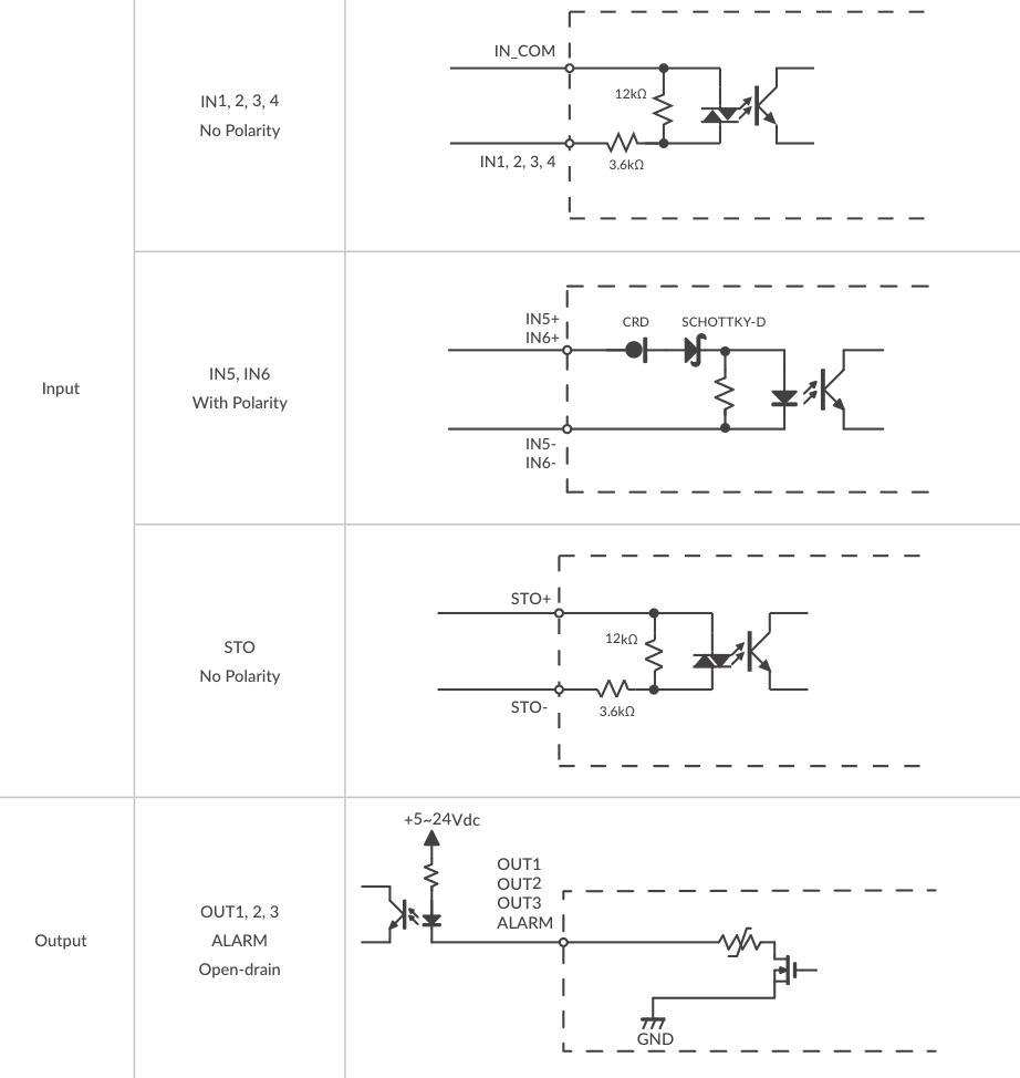
* When not using the STO function, apply a voltage of 5 to 24V between STO+ and STO-.
Pulse Type
In the Pulse Type, IN5 is the CCW / Dir / A-Phase pulse input and IN6 is the CW / Step / B-Phase pulse input. See Circuit Connection for the line driver and open collector pulse input circuits.
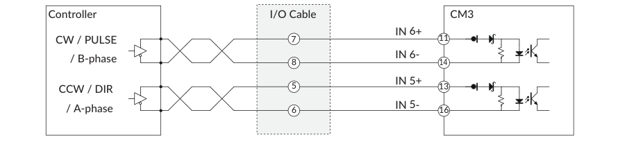
Circuit Connection
Pulse Input (Pulse Type)
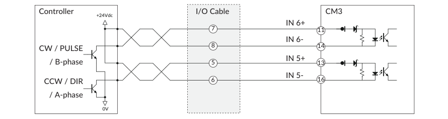
CM3 supports line driver output or open collector output pulse signals.
Input Pulse Maximum Frequency: 1 [MHz]
Line Driver Output
Open Collector Output
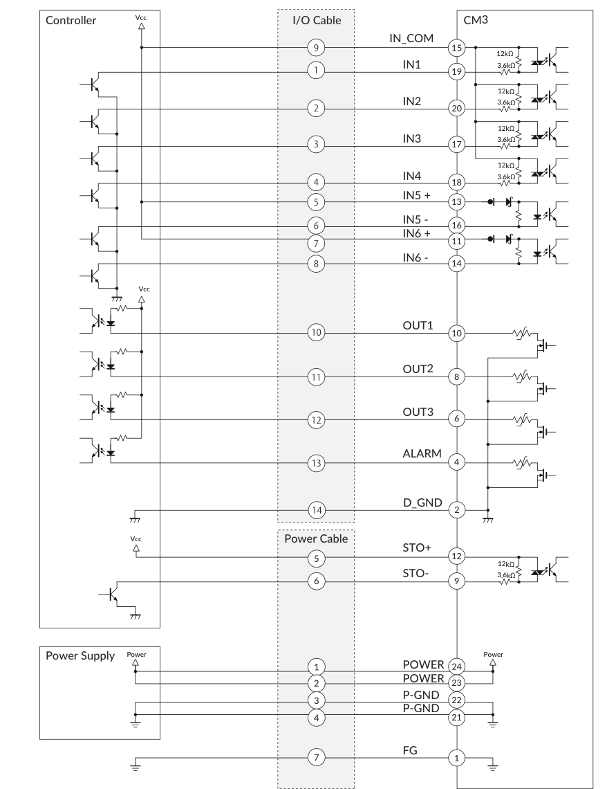
Connection Example with Sink Output Circuit (I/O and Direct Type)
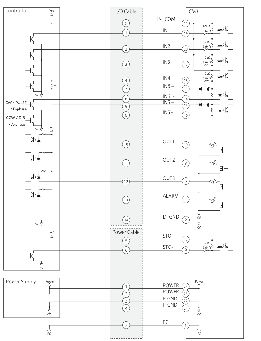
Connection Example with Sink Output Circuit (Pulse Type)
Connection Example with Source Output Circuit (I/O and Direct Type)
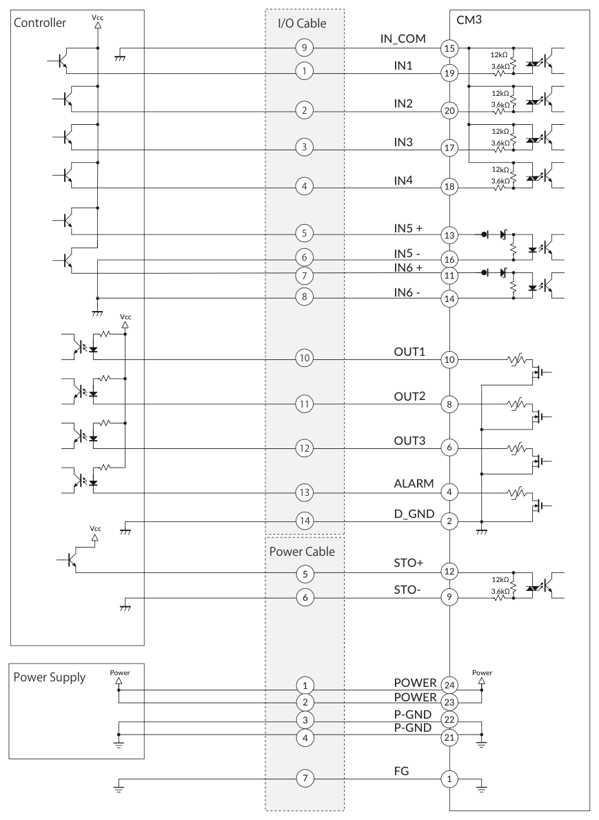
Connection Example with Source Output Circuit (Pulse Type)
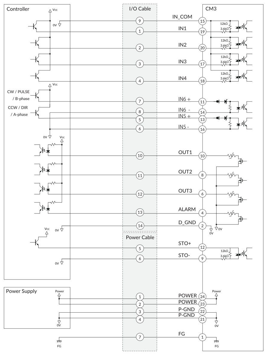
Make sure that the power is OFF while connecting the cables. Power ON after confirming the wiring is thoroughly correct.
Make sure to ground the FG.