

Overview
The programming language CML via RS-232C serial communication can control CM3. MUSCLE developed CML based on ASCII code, the most widely used character-encoding scheme for computer and communication devices. CML is composed of combinations of ASCII character codes. For the ASCII code chart, see Appendices.
CML is composed of parameters, Motion Data, execution commands and Query commands. CML and character codes are shown in the below table.
Pulse Type
On the Pulse Type, positioning is commanded by pulse input signals, so Motion Data is not used. CML on the Pulse Type covers parameter settings, a small set of execution commands ($, O, F) and Query commands, which are convenient when starting up the device. As the flow to operation, set the operating conditions by parameters, then operation can be executed by applying pulse signals.
|
CML Command |
Character Code |
Function |
Others |
Applies to |
|---|---|---|---|---|
|
Parameters Ref: Parameter Settings |
K** |
Motion Environmental Parameters |
K1 - K15 |
All |
|
Origin Detection Parameters |
K22 - K30 |
I/O・Direct |
||
|
Gain Adjustment Parameters |
K31 - K36 |
All |
||
|
I/O Parameters |
K42 - K60 |
All |
||
|
Status Parameters |
K61 - K66 |
All |
||
|
Communication Parameters |
K71 - K73 |
Direct |
||
|
Monitoring Parameters |
K85 - K90 |
I/O・Direct |
||
|
Motion Data Ref: Motion Data |
V** |
Motion Mode |
Motion Data 0 to 7 (I/O) or 0 to 31 (Direct). Motion patterns for max. 8 (I/O) / 32 (Direct) positions can be set. |
I/O・Direct |
|
P** |
Position Data |
I/O・Direct |
||
|
S** |
Speed Data |
I/O・Direct |
||
|
A** |
Acceleration Data |
I/O・Direct |
||
|
D** |
Deceleration Ratio Data |
I/O・Direct |
||
|
M** |
Torque Limit Data |
I/O・Direct |
||
|
Q** |
Push Motion Torque Data |
I/O・Direct |
||
|
ZL** |
Individual ZONE(―) |
I/O・Direct |
||
|
ZH** |
Individual ZONE(+) |
I/O・Direct |
||
|
Execution Commands Ref: Execution Commands |
^** |
Motion Data Execution |
|
Direct |
|
] |
Stop, Cancel Warning |
|
Direct |
|
|
| |
Origin Detection Execution |
|
Direct |
|
|
[ |
Restart |
|
Direct |
|
|
( |
Servo On, Alarm Reset |
|
Direct |
|
|
) |
Servo Off |
|
Direct |
|
|
# |
Teaching |
|
Direct |
|
|
$ |
Save Parameters & Motion Data |
|
All |
|
|
O |
Output Signal On |
|
All |
|
|
F |
Output Signal Off |
|
All |
|
|
Query Command Ref: Query Commands |
?** |
Current Status |
|
All |
** = Number
Procedure from setting to operation
-
Parameter settings — Set the operating environment such as Resolution and speed unit.
-
Motion Data settings (I/O and Direct Type) — Set Motion Data such as target position, velocity, and acceleration.
-
Operation — I/O Type: after saving the set parameters and Motion Data in CM3, execute the Motion Data from Input signals. Direct Type: after saving the set parameters and Motion Data in CM3, execute the Motion Data by execution commands. Pulse Type: operation is executed by applying pulse signals.
-
Check the Motor Status with a Query Command — Query commands allow to confirm the set data and various information such as the current position, speed, and torque.
CML allows to build a simple system by creating a sequence using I/O signals, execution commands and Query commands on host devices such as PLC, PC, HMI, and microcomputer.
Parameter Settings
Set parameters such as Resolution, communication settings, and protection function. Details of various functions and usage examples are described on the Detail of Various Settings page. The format for setting/checking using CML parameters is as follows.
Pulse Type
The list of parameters will be displayed by clicking "ALL" in the "Parameter" window of COOL WORKS QUICK. Please set up CM3 following the details of each function and the examples stated on the Detail of Various Settings page.
Setting Format
K Parameter Number = Value [CRLF]
Confirmation Format
K Parameter Number [CRLF]
Setting Example: When setting 10000 pulse to the Software Limit in positive coordinate and the Software Limit valid.
K10=100[CRLF]    // * The pulse unit of the Software Limit is 100 pulses
K7=1[CRLF]
The above data can be set by sending CML commands to CM3.
Confirming Example: To confirm whether the Software Limit function is valid.
K7[CRLF]         //Send to CM3
K7.1=1[CRLF]     //Sent from CM3 to host
Note
-
Please change parameters while CM3 is stopped.
-
The changed parameter value is saved by executing the Data Save command ($).
-
Unless the Data Save command is executed, the value saved previously will remain when the power is turned on again.
-
For safety reasons, there are some settings that require a power off and on (Restart). These are marked with ✓ in the Restart column of the parameter tables below.
Numbers for Parameter Setting
If B0 to B# is written in the Setting/Range in the following Parameter List, the setting is made in bit units.
|
Bit |
B7 |
B6 |
B5 |
B4 |
B3 |
B2 |
B1 |
B0 |
|---|---|---|---|---|---|---|---|---|
|
Binary |
0 |
1 |
0 |
0 |
1 |
1 |
0 |
0 |
The contents set to 1 are valid, and the contents set to 0 are invalid. When setting parameters, convert the binary number to decimal number before setting.
Example: Binary number: 01001100b ⇒ Decimal number: 76 ⇒ K##.1 = 76[CRLF]
-
Separate CML data commands with CR or CRLF.
-
The description of CR and CRLF is omitted in this document.
Motion Environmental Parameters
|
K |
Name |
Setting/Range |
Unit |
Restart |
Applies to |
Reference/Remarks |
|---|---|---|---|---|---|---|
|
1 |
Resolution |
0: 300 1: 600 2: 1000 3: 1200 4: 2000 5: 3000 6: 5000 7: 6000 8: 10000 9: 12000 |
ppr |
✓ |
All |
Set the pulse count per revolution. The Resolution of the ABZ encoder is max. 3000 ppr and the same Resolution as the Resolution parameter is applied. When Resolution is set higher than 3000 ppr, the max. 3000 ppr is applied to the ABZ encoder Resolution. Ref: Resolution (K1) on the Detail of Various Settings page |
|
2 |
Speed Unit |
0: 100 1: 10 2: 1 |
pps |
✓ |
I/O・Direct |
Set the speed unit for S command. |
|
3 |
Servo ON/OFF Setting |
0: Servo Off 1: Servo On |
|
|
All |
Set either CM3 starts with Servo on or Servo off when powered on. |
|
4 |
Coordinate Direction |
0: Positive in CW 1: Positive in CCW |
- |
✓ |
I/O・Direct |
Set the coordinate direction. Ref: Coordinate Direction (K4) on the Detail of Various Settings page |
|
5 |
In-position Range |
1 - 500 |
Pulse |
|
All |
Set the range for In-position. Ref: In-position (K5) on the Detail of Various Settings page |
|
6 |
Speed Override |
1 - 100 |
% |
|
I/O・Direct |
Limit the speed by the set proportion. Ref: Speed Override (K6) on the Detail of Various Settings page |
|
7 |
Software Limit Setting |
0: Disabled 1: Detect before moving 2: Detect after moving |
- |
|
I/O・Direct |
Set the enable / disable of the software limit function and the operation when the function is enabled. Ref: Software Limit (K7, K8, K9, K10) on the Detail of Various Settings page |
|
8 |
Software Limit(+) |
0 - Depends on Resolution |
Pulse (set by K10) |
|
I/O・Direct |
Set the operating limit boundary in the positive direction (unit set by K10). Ref: Software Limit (K7, K8, K9, K10) on the Detail of Various Settings page |
|
9 |
Software Limit(―) |
Depends on Resolution - 0 |
Pulse (set by K10) |
|
I/O・Direct |
Set the operating limit boundary in the negative direction (unit set by K10). Ref: Software Limit (K7, K8, K9, K10) on the Detail of Various Settings page |
|
10 |
Unit of Software Limit |
0: 100 1: 10 2: 1 |
Pulse |
✓ |
I/O・Direct |
Set the unit for Software Limit. Ref: Software Limit (K7, K8, K9, K10) on the Detail of Various Settings page |
|
11 |
Push Motion Operation Mode |
0: Continuous (One direction) 1: Set time (One direction) 2: Continuous (Both direction) 3: Set time (Both direction) |
- |
|
I/O・Direct |
Set the direction and time for Push Motion. ( ): Direction to limit torque. One direction: torque is limited only in operation direction. Both direction: torque is limited in both directions. Ref: Push Motion on the Various Functions page |
|
12 |
Torque Limit |
0 - 100 |
% |
|
Pulse |
Set the limit to output torque by a signal to Input 4 by the ratio to the maximum torque. Ref: Torque Limit (Pulse Type) on the Various Functions page |
|
13 |
Push Motion Holding Time |
1 - 30000 |
msec |
|
I/O・Direct |
Set Push Motion Holding Time. Ref: Push Motion on the Various Functions page |
|
14 |
Open Loop Holding Angle |
0: Disabled 1 - 72 |
± 0.1° |
|
I/O・Direct |
Set the angle difference between the target and current position to switch back to closed loop from Open Loop Holding. Ref: Open Loop Holding (K14, K15) on the Detail of Various Settings page |
|
15 |
Switch Time for Open Loop Holding Mode |
10 - 1000 |
msec |
|
I/O・Direct |
Set the time to switch to Open Loop Holding after positioning is completed. Ref: Open Loop Holding (K14, K15) on the Detail of Various Settings page |
Origin Detection Parameters (I/O and Direct Type)
|
K |
Name |
Setting/Range |
Unit |
Restart |
Applies to |
Reference/Remarks |
|---|---|---|---|---|---|---|
|
21 |
Origin Detection Execution |
0: Disable 1: Enable |
|
|
I/O |
Sets disable / enable of origin detection by signal to Input 6. Ref: Origin Detection on the Various Functions page |
|
22 |
Origin Signal Source |
0: Stopper Detection 1: Stopper Detection (Auto) 2: Origin Sensor 3: Origin Sensor (Auto) 4: Stopper Detection & Z Phase 5: Stopper Detection & Z Phase (Auto) 6: Origin Sensor & Z Phase 7: Origin Sensor & Z Phase (Auto) 8: Z Phase Signal 9: Z Phase Signal (Auto) |
- |
✓ |
I/O・Direct |
Set the signal source and method of the Origin Detection. Origin sensor can be assigned only to Input 1. Auto: Origin Detection starts automatically when power is on. Ref: Origin Detection on the Various Functions page |
|
23 |
Origin Detection Speed |
1 - 32767 |
pps (set by K2) |
|
I/O・Direct |
Set the speed for Origin Detection. |
|
24 |
Origin Detection Acceleration |
1 - 32767 |
kpps² |
|
I/O・Direct |
Set the acceleration for Origin Detection. |
|
25 |
Origin Detection Direction |
0: CW 1: CCW |
- |
✓ |
I/O・Direct |
Set the direction for Origin Detection. |
|
26 |
Origin Offset Distance |
± 32767 |
pulse |
|
I/O・Direct |
Set offset amount from detected origin to coordinate origin. |
|
27 |
Unit of Origin Offset Distance |
0: 100 1: 10 2: 1 |
pulse |
✓ |
I/O・Direct |
Set the unit when Offset is set. |
|
28 |
Stopper Detection Torque |
10 - 150 |
% |
|
I/O・Direct |
Set the torque to detect a stopper for Origin Detection by percentage to rated torque. Ref: Stopper Detection on the Various Functions page |
|
29 |
Single Turn ABS Function |
0: Disabled 1: Enabled |
- |
✓ |
I/O・Direct |
Set enable / disable of the Single Turn ABS function. Ref: Single Turn ABS Function (K29) on the Detail of Various Settings page |
|
30 |
Origin Detection Completion |
0: Disabled 1: Enabled |
- |
✓ |
I/O・Direct |
Function will not be operated until origin detection is completed. Ref: Origin Detection Completion (K30) on the Detail of Various Settings page |
Gain Adjustment Parameters
|
K |
Name |
Setting/Range |
Unit |
Restart |
Applies to |
Reference/Remarks |
|---|---|---|---|---|---|---|
|
31 |
Tuning |
0: PPI 1: Tuningless |
- |
|
All |
Set CM3's Tuning method. Ref: Tuning on the Various Functions page |
|
32 |
Servo Stiffness |
I/O・Direct: 10 - 200 Pulse: 30 - 150 |
|
|
All |
Set Servo Stiffness when Tuningless is selected. Ref: Tuningless (K31=1) on the Various Functions page |
|
33 |
Position P Gain |
1 - 5000 |
|
|
All |
Set 3 types of gains when PPI is selected. Ref: PPI (K31=0) on the Various Functions page |
|
34 |
Speed P Gain |
50 - 5000 |
|
|
All |
Set 3 types of gains when PPI is selected. Ref: PPI (K31=0) on the Various Functions page |
|
35 |
Speed I Gain |
0 - 5000 |
|
|
All |
Set 3 types of gains when PPI is selected. Ref: PPI (K31=0) on the Various Functions page |
|
36 |
S-Curve Gain |
0 - 1024 |
|
|
I/O・Direct |
Set S-Curve Gain for positioning operation. Ref: S-Curve Gain on the Various Functions page |
I/O Parameters
|
K |
Name |
Setting/Range |
Unit |
Restart |
Applies to |
Reference/Remarks |
|---|---|---|---|---|---|---|
|
41 |
Pulse Input Method |
0: CW/CCW 1: Step/Direction 2: A Phase/B Phase |
|
✓ |
Pulse |
Select Pulse Input Method from CW/CCW, Step/Direction or A Phase/B Phase. Ref: Pulse Input Method (K41) on the Detail of Various Settings page |
|
42 |
Input Filter |
1 - 50 |
msec |
✓ |
All |
Set the filtering time for input signal. Ref: Input Filter on the Various Functions page |
|
43 |
Input Logic |
1st digit: IN 1 2nd digit: IN 2 3rd digit: IN 3 4th digit: IN 4 5th digit: IN 5 6th digit: IN 6 |
0: Active High 1: Active Low |
✓ |
All |
Set the input logic. Ref: Input Logic on the Input/Output page. Ex: IN1, IN3, and IN5 as Active Low: K43=010101 |
|
44 |
Input 1 Function |
0: No Action 1: Origin Sensor (only for IN1) 2: CCW Limit Sensor 3: CW Limit Sensor |
|
✓ |
I/O・Direct |
Assign a function to Input 1. On the I/O Type, Inputs 1 & 5 are assignable (K44/K48) and the functions of the other inputs are fixed. On the Direct Type, Inputs 1 & 2 are assignable (K44/K45) and the functions of Inputs 3 to 6 are fixed. Ref: Input Functions on the Various Functions page |
|
45 |
Input 2 Function |
0: No Action 2: CCW Limit Sensor 3: CW Limit Sensor (1: Origin Sensor is only for IN1) |
|
✓ |
Direct |
Assign a function to Input 2. Ref: Input Functions on the Various Functions page |
|
48 |
Input 5 Function |
0: No Action 2: CCW Limit Sensor 3: CW Limit Sensor (1: Origin Sensor is only for IN1) |
|
✓ |
I/O |
Assign a function to Input 5. Ref: Input Functions on the Various Functions page |
|
50 |
Inching・Jog Speed |
1 - 32767 |
pps (set by K2) |
|
Direct |
Set the speed for the Inching and Jog operation. Ref: Manual Mode on the Various Functions page |
|
51 |
Inching Distance |
1 - 100 |
Pulse |
|
Direct |
Set the Inching distance. Ref: Manual Mode on the Various Functions page |
|
52 |
Inching・Jog Shift Time |
0: No Inching Motion 1 - 3000 |
msec |
|
Direct |
Set the time to switch to Jog from Inching completion. Ref: Manual Mode on the Various Functions page |
|
53 |
Output Logic |
1st digit: OUT 1 2nd digit: OUT 2 3rd digit: OUT 3 |
0: Active High 1: Active Low |
✓ |
All |
Set the output logic. Ref: Output Logic on the Input/Output page. Ex: OUT3 and OUT1 as Active Low: K53=101 |
|
54 |
Output Function |
0: ABZ Encoder Output 1: User Defined |
|
✓ |
All |
Select the function to be assigned to outputs 1 to 3 from "ABZ Encoder Output" and "User Defined". Ref: Output Functions on the Various Functions page |
|
55, 56, 57 |
Output 1 / 2 / 3 Function |
0: General Output 1: In-position Output 2: Warning Output 3: Individual ZONE Output 4: ZONE Output 5: MOVE Output 6: BUSY Output 7: END Output 8: Servo On Output 9: Push Motion Output 10: Origin Set Completion Output |
|
|
All |
Assign functions to Output 1 to 3 when "User Defined" is selected. Ref: Other Output Functions on the Various Functions page |
|
58 |
MOVE Output Threshold |
0 - 2147483648 |
pps (set by K2) |
|
All |
Set the speed threshold to output MOVE Output signal. Ref: Other Output Functions on the Various Functions page |
|
59 |
ZONE(―) |
± 2147483647 |
Pulse |
|
I/O・Direct |
Set boundary of ZONE Output in the negative direction. Ref: Other Output Functions on the Various Functions page |
|
60 |
ZONE(+) |
± 2147483647 |
Pulse |
|
I/O・Direct |
Set boundary of ZONE Output in the positive direction. Ref: Other Output Functions on the Various Functions page |
Status Parameters
|
K |
Name |
Setting/Range |
Unit |
Restart |
Applies to |
Reference/Remarks |
|---|---|---|---|---|---|---|
|
61 |
Temperature Warning Threshold |
0 - 100 |
℃ |
|
All |
Set the threshold to output a temperature warning. |
|
62 |
Load Warning Threshold |
0 - 100 |
% |
|
All |
Set a threshold to output a load warning as a percentage of the maximum torque. |
|
63 |
Position Error Overflow Threshold |
1 - 32767 |
1000 pulse |
|
All |
Set Position Error Overflow Threshold between current and target position. Ref: Position Error Overflow Threshold (K63) on the Detail of Various Settings page |
|
64 |
Overload Detection Time |
100 - 10000 |
msec |
|
All |
Set the time to output Overload alarm. Ref: Overload Detection Time (K64) on the Detail of Various Settings page |
|
65 |
Status LED |
0: Enabled 1: Disabled |
|
|
All |
Set enable / disable of the status LED. Ref: Status LED on the Various Functions page |
|
66 |
Status Report |
B0: In-position/Alarm (Ux.1) B1: Input Status (IN.1) B2: Output Status (OUT.1) B3: No Local Echo B4: Comment B5: Warning (Ux.1) B6: N/A B7: N/A |
|
|
All |
Set the conditions to automatically report to a host controller. Ref: Status Report (K66) on the Detail of Various Settings page |
Communication Parameters (Direct Type)
|
K |
Name |
Setting/Range |
Unit |
Restart |
Applies to |
Reference/Remarks |
|---|---|---|---|---|---|---|
|
71 |
Baud Rate |
0: 38.4 1: 9.6 2: 19.2 3: 57.6 4: 115.2 |
kbps |
|
Direct |
Set the baud rate. Ref: Baud Rate (K71) on the Detail of Various Settings page |
|
72 |
Parity |
0: None 1: Even 2: Odd |
|
|
Direct |
Set the parity when transferring data. |
|
73 |
Delimiter |
0: CR 1: CRLF |
|
|
Direct |
Set the delimiter type at the end of replied data from CM3. |
Monitoring Parameters (I/O and Direct Type)
|
K |
Name |
Setting/Range |
Unit |
Restart |
Applies to |
Reference/Remarks |
|---|---|---|---|---|---|---|
|
85 - 88 |
CH0 - CH3 Data |
0: Disabled(-) 1: Target Position (pulse) 2: Current Position (pulse) 3: Target Speed (K2 value) 4: Current Speed (K2 value) 5: Target Torque (% to Max Torque) 6: Current Torque (% to Max Torque) 7: Load Factor (% to Rated Torque) 8: Voltage (0.1V) 9: Temperature (℃) 10: Input Status(-) 11: Output Status(-) |
|
|
I/O・Direct |
Output data can be set up to 4 channels. Ref: Streaming Data on the Various Functions page |
|
89 |
Streaming Interval |
I/O: 100 (cannot be changed) Direct: 1 - 30000 |
msec |
|
I/O・Direct |
Set time interval to output Streaming Data. Ref: Streaming Data on the Various Functions page |
|
90 |
Streaming Setting |
0: Disabled 1: Streaming all the time 2: Streaming while operation |
|
|
I/O・Direct |
Set the timing to stream data (cannot be saved). Ref: Streaming Data on the Various Functions page |
Motion Data (I/O and Direct Type)
By setting specific Motion Data such as speed, acceleration, and target position, the CM3 can perform the desired positioning operation. CM3 supports normal positioning, relative positioning, and push motion.
I/O Type
Up to 8 Motion Data can be set, numbered 0 to 7. The stored Motion Data is selected and started by input signals. See Positioning Operation on the Various Functions page.
Direct Type
Up to 32 Motion Data can be set, numbered 0 to 31. Motion Data is executed by the ^ command. First, let's set the data as follows.
V0=0        // Set PTP Motion to Motion Mode
S0=100      // Set speed to 100
A0=50       // Set acceleration to 50
M0=70       // Set 70% for maximum torque
P0=10000    // Set 10000 pulses as the target position
^0          // Execution
When the motion is executed, CM3 moves toward the target position 10000 [pulse] at the set speed and acceleration. When the positioning is completed, CM3 sends the status Ux.1=8 indicating the in-position.
Each Motion Data consists of the items listed below.
|
Command |
No. |
Name |
Setting/Range |
Unit |
|---|---|---|---|---|
|
V |
0 - 7 (I/O) 0 - 31 (Direct) |
Motion Mode |
0: PTP Motion 1: INC Motion 2: PTP Push Motion 3: INC Push Motion |
- |
|
P |
Position Data |
Depends on Resolution (Ref: Resolution (K1) on the Detail of Various Settings page) |
pulse |
|
|
S |
Speed Data |
± 200000 (Ref: Resolution (K1) on the Detail of Various Settings page) |
Set by K2 |
|
|
A |
Acceleration |
1 - 32767 |
kpps² |
|
|
D |
Deceleration Ratio |
1 - 150 |
% of A command |
|
|
M |
Torque Limit |
0 - 100 |
% of Max. Torque |
|
|
Q |
Push Motion Torque |
10 - 80 |
% of Rated Torque |
|
|
ZL |
Individual ZONE(―) |
Depends on Resolution (Ref: Resolution (K1) on the Detail of Various Settings page) |
pulse |
|
|
ZH |
Individual ZONE(+) |
Depends on Resolution (Ref: Resolution (K1) on the Detail of Various Settings page) |
pulse |
Definition of position, speed and acceleration
Position
Define a unit of angle that positioning can be executed as 1 pulse. The number of pulses per rotation of the output shaft is called Resolution and its unit is ppr (pulse per revolution). 1000 is set to Resolution as default setting and the Resolution can be set from 300 to 12000 ppr by parameter.
Speed
Define the number of pulses to move per second as 1 pps. The unit of speed is set as 100 pps and it is selected from 100 pps, 10 pps or 1 pps by parameter.
Example: When K2=0(100pps)and S=100
S.1 = 100 × 100pps = 10000 [pps]
Unit Conversion to rpm
Speed[rpm] = S Data × Speed Unit [pps] × 60 [sec/min] / Resolution [ppr]
Example: S Data 100(S=100), Speed Unit 100pps(K2=0), Resolution 1000ppr(K1=2)
Speed[rpm] = 100 × 100[pps] × 60[sec/min] / 1000[ppr] = 600 [rpm]
Acceleration
The rate of increase in velocity per second is defined as acceleration. The unit is pps² [pulse / sec²]. The unit of acceleration data "A" is kpps² (kilo-pulse/sec²) = 1000 [pps²].
Example: Speed Unit: 100pps(K2=0), Speed Data: 500(S=500), Acceleration Data: 100(A=100). The acceleration time to reach the target speed is:
Acceleration Time [sec] = 500 × 100 [pps] / (100 × 1000 pps²) = 0.5 [sec]
Setting Format
"CML command" Motion Data No. = Value
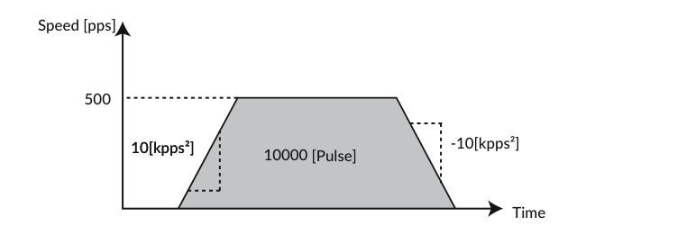
Example: Set 10000 pulse to Position, 5000 pps to Speed and 10 kpps² to Acceleration of Motion Data 2.
V2.1=0        //Set PTP Motion to Motion Type of Motion Data 2
P2.1=10000    //Set 10000 pulse to Position of Motion Data 2
S2.1=50       //Set 5000 pps to Speed of Motion Data 2 (Unit set by K2)
A2.1=10       //Set 10kpps² to Acceleration of Motion Data 2
D2.1=100      //Set 100% to Deceleration of Motion Data 2
Confirmation Format
"CML command" Motion Data No.1 *".1" is displayed for replied data
Example: Confirm the speed set in Motion Data 2
S2.1          //Confirm the Speed Data set in Motion Data 2
S2.1=50       //Reply to host from CM3
Commands
Motion Mode Setting (V command)
Choose a motion mode from the below list.
|
V |
Contents |
Detail |
|---|---|---|
|
0 |
PTP Motion |
Absolute positioning motion to the target position set by the P command with reference to the origin |
|
1 |
INC Motion |
Incremental positioning motion to move the distance set by the P command from the current position |
|
2 |
PTP Push Motion |
PTP Motion with the limited torque by Q command |
|
3 |
INC Push Motion |
INC Motion with the limited torque by Q command |
Example:
V0=0    // Set the motion mode of Motion Data 0 to PTP Motion
V3=1    // Set the motion mode of Motion Data 3 to INC Motion
Position Setting (P command)
Set the target position with respect to the origin for PTP Motion, and set the relative motion distance from the current position for INC Motion.
Example:
P1=1000          // Set 1000 pulses as the target position of Motion Data 1
P7=1000000000    // Set continuous motion for Motion Data 7
-
When 10⁹ is set to the target position (P=1000000000), the motion will be the continuous motion. For continuous motion, rotation direction is set only by S command. Regardless of the coordinate direction (K4) setting, when the S command has a positive value, the output shaft rotates in the CW direction, and when it has a negative value, it rotates in the CCW direction.
-
The settable range of position data depends on the Resolution. Please refer to Resolution(K1) on the Detail of Various Settings page for details.
-
If the current position exceeds the settable range of coordinates due to INC Motion or continuous operation, executing PTP Motion from that position may move in an unexpected direction.
I/O Type
PTP operation from a position beyond the coordinate range is not possible.
Direct Type
Be sure to reset the current position if the coordinate range is exceeded.
Speed Setting (S command)
Set the target speed of the motion as a positive value. If the acceleration is small with respect to the distance traveled, deceleration will start before the set value is reached. The unit is selected from 100 pps, 10 pps, and 1 pps according to the speed unit parameter (K2).
Ex 1:
S1=100 // Set 100 (unit: K2) as the target speed of Motion Data 1
Ex 2:
P6=1000000000    // Set continuous operation for Motion Data 6
S6=-100          // Set 100 (unit: K2) as the continuous motion speed of Motion Data 6 in the CCW
* Set a negative value for speed data only for continuous operation in the CCW direction.
Acceleration Setting (A command)
Sets the acceleration of motion.
Example:
A0=100 // Set 100 kpps² as the acceleration of Motion Data 0
Deceleration Setting (D command)
Set the deceleration as a ratio to the acceleration.
Example:
A2=100    // Set 100 kpps² as the acceleration of Motion Data 2
D2=50     // Set the deceleration of Motion Data 2 to 50% of the A2
Torque Limit Setting (M command)
The output torque during motion can be limited by the ratio to the maximum torque.
Example:
M5=80 // Limit the output torque in Motion Data 5 to 80% of the maximum torque
Push Motion Torque Setting (Q command)
Set the torque for the push motion as a ratio to the rated torque when push motion is set by the Motion Mode. Please refer to Push Motion on the Various Functions page for details.
Example:
Q3=50 // Set the torque for push motion of Motion Data 3 to 50% of the rated torque
Individual Zone(―)(ZL command)
Sets the negative boundary point of the individual zone output. Please refer to Resolution(K1) on the Detail of Various Settings page for the settable value range of the position data, and to Other Output Functions on the Various Functions page for the details.
Example:
ZL6=5000 // Set 5000 pulses for Individual Zone(―)
Individual Zone(+)(ZH command)
Sets the positive boundary point of the individual zone output. Please refer to Resolution(K1) on the Detail of Various Settings page for the settable value range of the position data, and to Other Output Functions on the Various Functions page for the details.
Example:
ZH6=10000 // Set 10000 pulses for Individual Zone(+)
Execution Commands
Execution commands trigger actions in CM3. On the Pulse and I/O Types, they are used to save data and to turn general outputs on / off. The Direct Type adds commands to execute and stop motion, cancel alarms, etc. By using execution commands and Query commands together, it is possible to create a sequence operation on the host side.
Execution Format
"CML command" No *Number can be omitted when it is not required
Example:
$      // Save all the Parameters and Motion Data
^28    // Execute Motion Data 28 (Direct Type)
|
CML |
Name |
No |
Contents |
Applies to |
|---|---|---|---|---|
|
^ |
Motion Data Execution |
0 - 31 |
Execute the Motion Data by specified No. |
Direct |
|
] |
Stop・Cancel Alarm |
- |
][CRLF]: Pause motion. INC and push motion can be resumed. ][CRLF]][CRLF]: Complete stop of motion and cancellation of warning. |
Direct |
|
[ |
Restart |
- |
Resume paused motion |
Direct |
|
| |
Origin Detection |
- |
Start Origin Detection (set by K21 to K30). Ref: Origin Detection on the Various Functions page |
Direct |
|
|1 |
Move to Position 0 |
- |
Move to position 0 |
Direct |
|
|2 |
Reset Current Position |
- |
Reset the current position to 0. |
Direct |
|
$ |
Data Save |
- |
Save data *Make sure the motor is not running before sending the command. |
All |
|
) |
Servo OFF |
- |
Servo off |
Direct |
|
(0 |
Servo ON |
- |
Servo on (available only after alarm reset) |
Direct |
|
(1 |
Alarm Reset |
- |
Reset an alarm |
Direct |
|
# |
Teaching |
0 - 31 |
Capture current position to specified position memory (available only during Manual Mode). Ref: Manual Mode on the Various Functions page |
Direct |
|
O |
Output Signal On |
1 - 3 |
Turn on the specified output. Ref: Other Output Functions on the Various Functions page |
All |
|
F |
Output Signal Off |
1 - 3 |
Turn off the specified output. Ref: Other Output Functions on the Various Functions page |
All |
Query Commands
Query commands read the set data and current status of CM3.
Status Query Commands
Where the replied contents are shown as B0 to B#, the replied data is set by bit.
|
CML |
Name |
Unit |
Replied Contents |
Applies to |
|---|---|---|---|---|
|
?0 - ?7 (I/O) ?0 - ?31 (Direct) |
Motion Data |
N/A |
Display specified Motion Data |
I/O・Direct |
|
?50 |
Output Status |
N/A |
B0: Output 1 B1: Output 2 B2: Output 3 B3: Output 4 Display Output Status in hexadecimal. OUT.1 = Hex value. 0: Off / 1: On. Not available when set to ABZ encoder output. |
All |
|
?70 |
Input Status |
N/A |
B0: Input 1 B1: Input 2 B2: Input 3 B3: Input 4 B4: Input 5 B5: Input 6 B6: STO Signal B7: Over Current Signal B8: N/A B9: N/A B10: Input 5 Jog operation signal (Direct; N/A on I/O) B11: Input 6 Jog operation signal (Direct; N/A on I/O) Display Input Status in hexadecimal. IN.1 = Hex value. 0: Off / 1: On. Please reduce the acceleration for B7. |
All |
|
?71 |
Temperature in Driver Case |
℃ |
Temp.1=Value |
All |
|
?72 |
Power Voltage |
0.1V |
CVSEN.1=Value |
All |
|
?79 |
Load Factor |
% |
PWR.1=Value — Display percentage of rated torque |
All |
|
?85 |
Version Information |
N/A |
Display CM3 Version Information |
All |
|
?90 |
List of Parameters |
N/A |
Display the list of all K parameters |
All |
|
?95 |
Position Deviation |
Pulse |
Pe.1=Value |
All |
|
?96 |
Current Position |
Pulse |
Px.1=Value |
All |
|
?97 |
Current Speed |
Set by K2 |
Sx.1=Value |
All |
|
?98 |
Current Torque |
% |
Ix.1=Value — Display percentage of the Max. torque |
All |
|
?99 |
Motor Status |
N/A |
Display Motor Status in decimal. Ux.1 = Decimal value. Ref: Motor Status. The contents of the operation warning and status warning can be checked by ?199. |
All |
|
?199 |
Warning |
N/A |
Display the detail of the operation warning and status warning. WARN.1=[Hex data]. Ref: Warning |
All |
|
?1000 |
List of Motion Data |
N/A |
Display the list of all Motion Data |
I/O・Direct |
Bit-type replied data example — when B6, B3 and B2 are ON:
Binary  : 0100 1100
Decimal : 2⁶ + 2³ + 2² = 64 + 8 + 4 = 76
Hex     : 76 = 16 × 4 + 12 = 4C
Motor Status
Every motor status can be checked by the ?99 command.
Data format
Ux.1=[Decimal data]
|
Value |
Name |
Detail |
Classification |
Applies to |
|---|---|---|---|---|
|
0 |
Moving |
Motor is running or out of in-position range |
- |
All |
|
1 |
Position Error Overflow |
Alarm occurs when position deviation exceeds K63 setting |
Alarm |
All |
|
2 |
Overvoltage Alarm |
Alarm occurs when input voltage exceeds 30V |
Alarm |
All |
|
4 |
Overload Alarm |
Alarm occurs when the current torque exceeds the maximum torque for the time set by K64 |
Alarm |
All |
|
8 |
In-position |
When in-position range with servo on |
- |
All |
|
16 |
Servo off |
Servo-off |
- |
All |
|
32 |
Push Motion |
Push Motion |
- |
I/O・Direct |
|
32 |
Torque Limit |
Torque Limit is active |
- |
Pulse |
|
64 |
Overcurrent Alarm |
Alarm occurs when excessive current such as regenerative current flows |
Alarm |
All |
|
128 |
Temperature Alarm |
Alarm occurs when internal temperature exceeds 110°C |
Alarm |
All |
|
256 |
Operation Warning |
See Warning |
Warning |
All |
|
512 |
Low Voltage Alarm |
Alarm occurs when main power supply falls below 18V |
Alarm |
All |
|
1024 |
STO Activated |
STO signal is turned off. |
Alarm |
All |
|
2048 |
Status Warning |
See Warning |
Warning |
All |
|
4096 |
ABS Alarm |
When origin detection has not been completed after setting the single-turn ABS function (K29) to enable. |
Alarm |
I/O・Direct |
About Alarms
When an alarm occurs, the Ux value corresponding to the contents of the alarm is issued, the alarm output is turned on, and the servo is turned off. Remove the cause of the alarm before canceling the alarm.
Refer to Sequence to Reset Alarm on the Various Functions page for the sequence of alarm cancellation.
Warning
Warning information can be checked with the Warning Query Command, ?199. Since a warning is a state before an alarm, the motor will not servo off. Utilizing warnings will help preventive maintenance of equipment. The warnings and details are as follows.
Data Format
WARN.1=[Hex value]
|
Value |
Name |
Detail |
Classification |
Applies to |
|---|---|---|---|---|
|
B0 |
Push Motion Warning |
Reach the target position during Push Motion |
Operation Warning |
I/O・Direct |
|
B1 |
Software Limit Warning |
Execution command to the target position set over the software limit is sent |
Operation Warning |
I/O・Direct |
|
B2 |
Limit Sensor Warning |
Limit sensor is on |
Operation Warning |
All |
|
B3 |
Manual Mode Warning |
Execution Command is sent in Manual Mode |
Operation Warning |
I/O・Direct |
|
B4 |
Origin Detection Incomplete Warning |
An execution command is sent while the origin detection operation was not completed when the origin detection completion (K30) was enabled |
Operation Warning |
I/O・Direct |
|
B5 |
Execution Warning |
An operation command is sent when operation cannot be performed |
Operation Warning |
All |
|
B6 |
Temperature Warning |
Temperature inside of driver case exceeds the set value of K61 |
Status Warning |
All |
|
B7 |
Over Load Warning |
The load exceeds the set value of K62 |
Status Warning |
All |
The motor axis does not servo off even in a warning state.
Classification of warnings
-
Operation Warning — Operation Warning indicates an inoperable condition. Please check the cause of the operation warning. To reset the warning, please send the pause command ].1 (Direct Type).
-
Status Warning — This is a warning that the temperature or load factor has exceeded a threshold value. The status warning function is useful for preventive maintenance of equipment.