

This page describes the K parameters that configure the basic behavior of the CM3. Settings that apply only to some control types are marked in the heading. See the CML (COOL MUSCLE Language) page for the full parameter list and how to set parameters.
Resolution (K1)
Set the Resolution of the motor in pulse per rotation. The maximum and minimum value of the position (P command) for each Resolution is as shown in the below table.
|
Value |
Resolution |
Maximum value in the negative direction |
Maximum value in the positive direction |
Speed data value at 5000 rpm for 100 pps speed unit |
|---|---|---|---|---|
|
0 |
300 |
-12,884,901 |
12,884,901 |
250 |
|
1 |
600 |
-25,769,803 |
25,769,803 |
500 |
|
2 |
1000 |
-42,949,672 |
42,949,672 |
833 |
|
3 |
1200 |
-51,539,607 |
51,539,607 |
1000 |
|
4 |
2000 |
-85,899,345 |
85,899,345 |
1667 |
|
5 |
3000 |
-128,849,018 |
128,849,018 |
2500 |
|
6 |
5000 |
-214,748,364 |
214,748,364 |
4167 |
|
7 |
6000 |
-257,698,037 |
257,698,037 |
5000 |
|
8 |
10000 |
-429,496,729 |
429,496,729 |
8333 |
|
9 |
12000 |
-515,396,075 |
515,396,075 |
10000 |
* Continuous position (P=1000000000) is available for all Resolutions.
K1=2 // Set 1000 to the Resolution per rotation
Coordinate Direction (K4) (I/O and Direct Type)
Set which of the CW / CCW directions is positive.
|
0: Set CW direction as the positive |
1: Set CCW direction as the positive |
|---|---|
|
P=100: 100 pulses in CW |
P=100: 100 pulses in CCW |
|
P=-100: 100 pulses in CCW |
P=-100: 100 pulses in CW |

K4=1 // Set CCW direction as the positive direction
* When 10⁹ is set to the target position (P=1000000000), the motion will be the continuous motion. For continuous motion, the rotation direction is set only by the S command. Regardless of the Coordinate Direction (K4) setting, when the S command has a positive value the output shaft rotates in the CW direction, and when it has a negative value it rotates in the CCW direction.
In-position (K5)
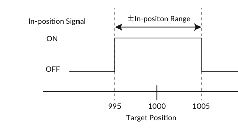
This parameter sets the range for In-position in the pulse unit. In-position is detected when the current position is within the set range against the target position. When stopping the motor by a stop command, the stopped position is recognized as the target position, therefore In-position is detected within the set range against the current position. When recognized as In-position, the In-position signal is ON and the motor status goes in Ux.1=8. The In-position signal can be output by assigning an output function. See Output Functions on the Various Functions page.
K5=5 // Set in-position range as +/- 5 pulses
In-position signals will be sent out between 995 and 1005, when the target position is 1000.
Speed Override (K6) (I/O and Direct Type)
The speed override can change the actual operating speed uniformly to the ratio to the set speed. In order to ensure the safety of the device, please set the speed override before trying the required speed. Without changing the value of the S command, you can test the motion at the speed that the speed override is applied. Gradually increase the ratio and check if there is any problem with the set S command data.
Operation Speed = Set Speed (S) × Speed Override (K6) / 100
K6=50 // A speed of 50% of the value of the S command is applied to the every motion
Software Limit (K7, K8, K9, K10) (I/O and Direct Type)
Please use the software limit function to prevent accidents when executing a set Motion Data. This function sets enable/disable of the limit of motion range, and how the motor behaves when the function is enabled.
Software Limit Setting (K7)
|
Value |
Setting |
Description |
|---|---|---|
|
0 |
Disable |
Disable the Software Limit |
|
1 |
Enable (no motion) |
Enable the Software Limit. If the motion to the outside of the Software Limit range is executed, the motor won't start moving, and Operation Warning (Ux.1=256) will be output. |
|
2 |
Enable (move to software limit) |
Enable the Software Limit. If the motion to the outside of the Software Limit range is executed, the motor moves to the boundary of the Software Limit range, and Operation Warning (Ux.1=256) will be output. |
* Software Limit does not work for Continuous Motion.
K7=1 // Set Software Limit as Enabled (no motion)
The motor does not start operating and outputs Ux.1=256 (Operation Warning) when it receives a command to execute the operation to the target position that exceeds the Software Limit set value. Then, WARN.1=2 (Software Limit Warning) is replied to the Query ?199 (Warning Information).
Software Limit Setting Range and Unit
From 0 position, set the positive operation boundary value to K8 Software Limit (+) and the negative operation boundary value to K9 Software Limit (−) with the unit set by K10. The set ranges are different by the unit as shown in the below table.
|
Positive (K8) |
Negative (K9) |
Unit (K10) |
|---|---|---|
|
0 to 9,999,999 |
-9,999,999 to 0 |
0: 100 pulse |
|
0 to 99,999,999 |
-99,999,999 to 0 |
1: 10 pulse |
|
0 to 999,999,999 |
-999,999,999 to 0 |
2: 1 pulse |
K8=100      // Set 10000 pulse to Software Limit (+)
K9=-150     // Set -15000 pulse to Software Limit (-)
K10=0       // Set 100 pulse to the Unit of Software Limit
Open Loop Holding (K14, K15) (I/O and Direct Type)
The Open Loop Holding is a function to automatically switch from closed loop control to open loop control if there is no operation command for the time set by the K15 parameter after positioning is completed. In Open Loop Holding mode, hunting inherent to the servo motor can be suppressed. If the difference between the current position and the target position becomes larger than the K14 set value (±0.1 to 7.2 degree) due to external force, the motor goes back in closed loop and returns to the previous target position.
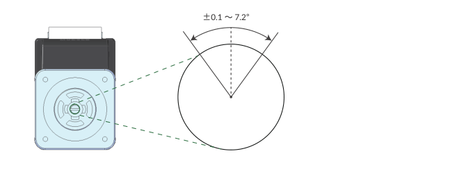
K14=10    // If the shaft is moved 1 degree by external force, it goes back in the closed loop
          // then goes back to previous target position
K15=500   // When there is no positioning command for 500 msec after positioning is completed,
          // CM3 goes in Open Loop Holding
Single Turn ABS Function (K29) (I/O and Direct Type)
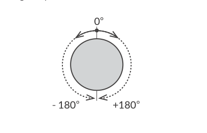
The Single Turn ABS function is a function that memorizes the position of the origin even after the power is turned off and can hold the position within ±180° with respect to the origin. In applications such as turntables, the time for origin detection can be omitted. However, if the stop position after the power is turned off is around 180 degrees from the origin, it will be an indefinite area, so when the power is turned off, stop as close to the origin as possible.
Steps to enable the Single Turn ABS Function
K29=1                     // Enable Single Turn ABS Function
$                         // Send Data Save command
Turn off / on the power
ABS Alarm is ON           (Ux.1=4096)
STO OFF & ON              // Servo ON (Ux.1=8)
Complete the Origin Detection.
* The origin is cleared when the origin signal source or origin detection direction is changed. Follow the above procedure again to set the origin. See Origin Detection on the Various Functions page.
Position value after turning on the power again
The current position when the power is turned on again is always -180° to +180° with respect to the origin. For example, for 1000 Resolution (K1=3), the current position after power on is a value from -500 to +500.
* Even if the output shaft rotates multiple times after the power is turned off, the position after the power is turned on again is converted into the range from -500 to +500.
-
Ex 1: If the power is turned on again at the position of Px.1 = 600, the current position will be Px.1 = -400.
-
Ex 2: If the power is turned on again at the position of Px.1 = 2300, the current position will be Px.1 = 300.
-
Ex 3: If the power is turned on again at the position of Px.1 = -1600, the current position will be Px.1 = 400.
Origin Detection Completion (K30) (I/O and Direct Type)
When the origin detection completion confirmation is enabled (K30=1) and the power is turned on again, only the origin detection operation is accepted until the origin detection is completed. If the execution command is issued when the origin detection is not completed, CM3 will not operate and Ux.1=264 (8: In-position + 256: Operation warning) will be output. When confirmed by the Query command ?199 (warning information), WARN.1=32 (operation warning) will be returned.
Pulse Input Method (K41) (Pulse Type)
The following Pulse Input Methods are available for CM3:
-
CW/CCW
-
Step/Direction
-
A Phase/B Phase
See Positioning Operation on the Various Functions page for details.
Position Error Overflow Threshold (K63)
Settable range: 1 to 32767
Unit: 1000 pulses
An error (Ux.1=1) is output when the deviation between the current position and the target position exceeds the set value, then the motor stops with Servo off.
K63=50 // Set Position Error Overflow Threshold as 50000 pulses
Overload Detection Time (K64)
Settable range: 100 to 10000
Unit: msec
Set the time until the overload alarm is output. If the overload state continues for the set time (msec), an overload alarm (Ux.1=4) is output, and the servo is turned off.
K64=3000    // When overload condition continues more than 3000 msec (3 sec),
            // the motor goes into an overload alarm status and stops with Servo off
Status Report (K66)
Set the conditions to automatically report to a host controller. When combining each condition, set the total value of each numerical value.
Ex 1: K66=13
-
2⁰ = 1 : Automatically report to a host when in-position and alarm occur.
-
2² = 4 : Automatically report to a host when output status changes.
-
2³ = 8 : No local echo
When 3 functions are combined, the value of K66 shall be 1+4+8=13 by addition.
Ex 2: K66=38
-
2¹ = 2 : Automatically report to a host when input status changes.
-
2² = 4 : Automatically report to a host when output status changes.
-
2⁵ = 32 : Automatically report to a host when warning occurs.
When 3 functions are combined, the value of K66 shall be 2+4+32=38 by addition.
|
Status Report |
Bit |
Ex1 |
Ex2 |
|---|---|---|---|
|
No Report |
0 |
|
|
|
In-position / Alarm |
B0 |
2⁰ = 1 |
|
|
Input Status |
B1 |
|
2¹ = 2 |
|
Output Status |
B2 |
2² = 4 |
2² = 4 |
|
No Local Echo |
B3 |
2³ = 8 |
|
|
Comment |
B4 |
|
|
|
Warning |
B5 |
|
2⁵ = 32 |
|
K66 Value |
|
13 |
38 |
Comment example
error.01.1: Value Out of Range!! // When a value outside the Motion Data setting range is entered
Baud Rate (K71) (Direct Type)
Set the baud rate for the communication to a host controller. When this parameter is changed, the host baud rate needs to be changed to match the changed baud rate.
|
Value |
Baud Rate [kbps] |
|---|---|
|
0 |
38.4 |
|
1 |
9.6 |
|
2 |
19.2 |
|
3 |
57.6 |
|
4 |
115.2 |
Caution
The set baud rate might not be available on some PCs and host instruments. Please enter a proper value that matches their specifications.
CM3's communication buffer could be overflowed by a delay of communication data processing when a lot of data are transferred to CM3 and over-written, then unexpected motion is possibly produced.
K71=1 // Set 9.6 kbps as the baud rate