

Mounting to Machinery
CM3 can be mounted either horizontally or vertically. Mount CM3 on the smooth and rigid surface of a metal plate. When installing CM3, insert the rabbet located on the motor's installation surface into the mounting plate's counterbore or through holes, then screw it with four bolts through the four mounting holes on CM3's installation surface, leaving no gaps between the surface and the metal plate.
Tolerance of the rabbet is stated on the Specifications page.
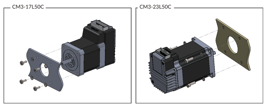
The sizes of the mounting bolts are as follows.
|
Model |
Bolt Size |
Depth |
|---|---|---|
|
CM3-17S50 / CM3-17L50 |
M3 |
4.0 mm |
|
CM3-23S50 / CM3-23L50 |
M4 |
- |
Be sure to mount the motor on a metal plate to dissipate heat. If the motor is mounted on plastic or other materials, it may cause a failure due to heat generation.
Mounting Metal Plate Reference Dimension
|
Model |
Dimension |
|---|---|
|
CM3-17S50 / CM3-17L50 |
100 x 100 x 2 mm |
|
CM3-23S50 / CM3-23L50 |
160 x 160 x 6 mm |
Mounting to Load
Attach the coupling to the output shaft and adjust so that the load shaft and output shaft are centered. Flexible coupling with torsional rigidity is recommended. Design the machinery and align the assembly to ensure that radial load and thrust load on the motor shaft do not exceed the allowable values. (Allowable radial load and thrust load of each CM3 motor size are stated on the Specifications page.)
-
Radial Load (Fr): Perpendicular force applied to the shaft end.
-
Thrust Load (Ft): Parallel force applied to the shaft end.
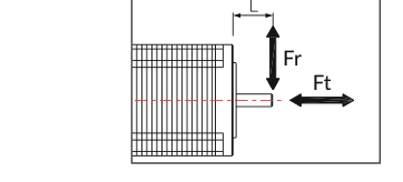
Mounting a load directly to the output shaft would increase the force and damage the motor. Consider reviewing the mechanical system so that excessive load is not applied to the output shaft.
Load Installations to Avoid
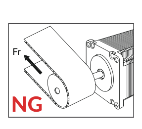
When a pulley is directly mounted onto the output shaft, radial force (Fr) will be produced by belt tension and may result in damaging bearings in the motor.
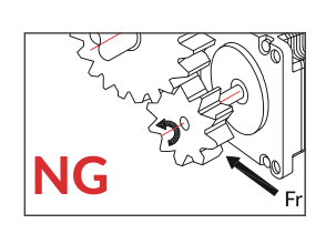
When a gear is directly mounted onto the output shaft, the smaller the dimensions of the gear, the bigger the radial force (Fr) that will be produced, and it may result in damaging bearings in the motor.
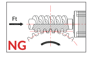
When a worm gear is directly mounted onto the output shaft, thrust load (Ft) will be produced and forced onto the motor shaft. The motor shaft will be moved, and it may result in damaging the inside of the motor.