

This page is a self-contained handbook for the CM3 I/O Type control mode: what it is, how to set it up, how to wire it, how to operate it by input signals, and a worked example. Material that also appears on the common pages is repeated here on purpose so that an I/O Type user can work from this single page; italic cross-references point to the common pages with full detail.
What is the I/O Type
The I/O Type CM3 can select and execute up to 8 points of Motion Data set from the PC by input signals. Each Motion Data is composed of the necessary items for motion such as speed, acceleration, target position, etc.
The Motion Data points (numbered 0 to 7) are created once over RS-232C serial communication using CML (COOL MUSCLE Language) or the free COOL WORKS QUICK software, and saved in the motor. During operation no serial communication is needed: a host device such as a PLC selects a Motion Data number with a 3-bit binary code on inputs IN2 to IN4 and executes it by applying a Start signal to IN6. This makes the I/O Type the natural choice when the motor is driven from PLC digital outputs.
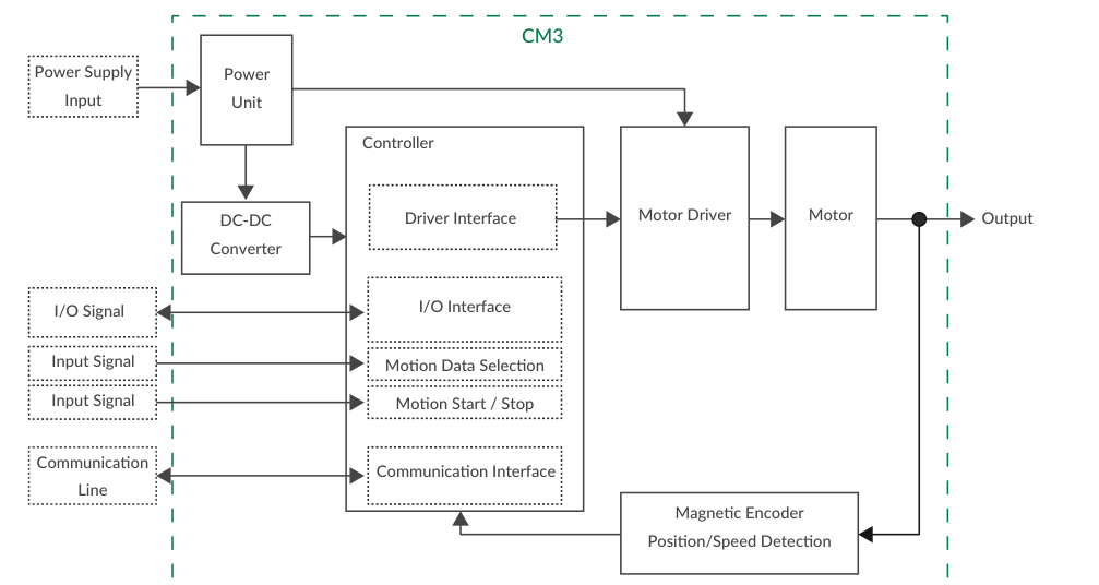
Main functions available in the I/O Type:
-
PTP Motion (absolute positioning)
-
Continuous Motion
-
Push Motion
-
Origin Detection
-
Software Limit
-
STO (Safe Torque Off) Function
-
Tuningless Function
-
Various Output Functions
Tip
In the I/O Type, serial communication is only required for setup (creating Motion Data and setting parameters). Once the data is saved with the $ command, the motor runs entirely from digital I/O — no programming is executed over RS-232C during operation.
General product structure, parts description and rotating direction: CM3 – Functions and Structure.
Setting Up
Connect with COOL WORKS QUICK and Select the I/O Type
COOL WORKS QUICK (hereafter CWQ) is CML-compatible utility software with a user-friendly interface that assists easy operation of CM3. With CWQ you can easily set and save parameters and Motion Data, stream data in a graph, etc. The latest version of CWQ and its manual are available for free on MUSCLE CORPORATION's website (https://musclecorp.com/motion-en).
Connect the PC to CM3 with Communication Cable A (CMRSA1) and power CM3 from a +24Vdc supply. If the following information is displayed when powered on, communication between PC and CM3 is established.
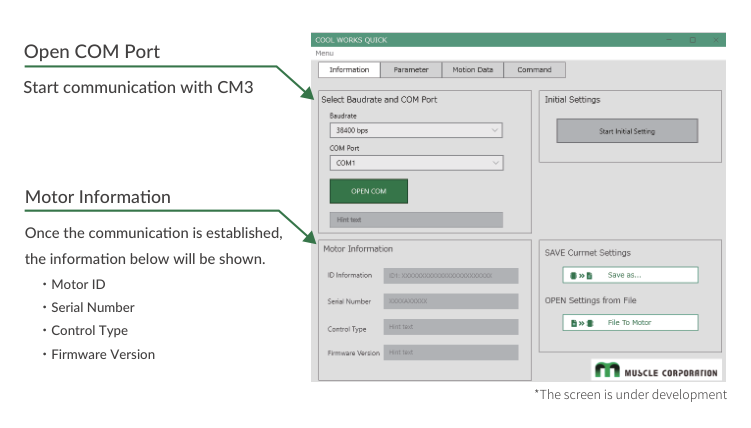
For host devices such as PLC and HMI, or Windows terminal software such as Tera Term, the communication conditions must be set as follows.
|
Baud rate |
38400 |
|
Data |
8 |
|
Parity |
NONE |
|
Stop |
1 |
|
Flow Control |
NONE |
Once communication is established, select the control type from the Initial Setup Wizard:
-
Click the button to open the Initial Setup Wizard.
-
When the Initialization Wizard opens, select the control type. The Pulse Type is selected as default — select the I/O Type.
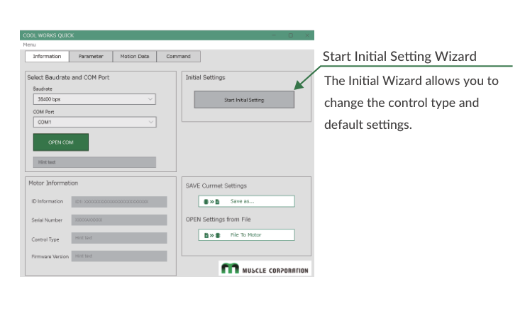
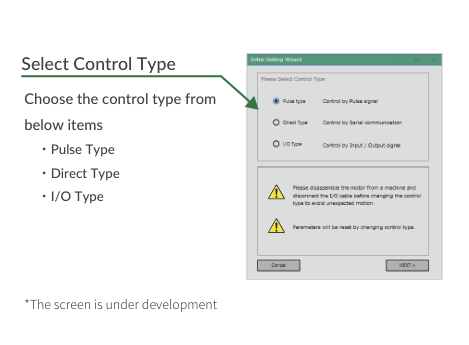
Full communication setup detail: CM3 – Communication Functions.
Creating Motion Data
Up to 8 Motion Data can be set, numbered 0 to 7. Each Motion Data consists of the items listed below.
|
Command |
No. |
Name |
Setting/Range |
Unit |
|---|---|---|---|---|
|
V |
0–7 |
Motion Mode |
0: PTP Motion / 1: INC Motion / 2: PTP Push Motion / 3: INC Push Motion |
– |
|
P |
0–7 |
Position Data |
Depends on Resolution (K1) |
pulse |
|
S |
0–7 |
Speed Data |
±200000 |
Set by K2 |
|
A |
0–7 |
Acceleration |
1 – 32767 |
kpps² |
|
D |
0–7 |
Deceleration Ratio |
1 – 150 |
% of A command |
|
M |
0–7 |
Torque Limit |
0 – 100 |
% of Max. Torque |
|
Q |
0–7 |
Push Motion Torque |
10 – 80 |
% of Rated Torque |
|
ZL |
0–7 |
Individual ZONE (−) |
Depends on Resolution (K1) |
pulse |
|
ZH |
0–7 |
Individual ZONE (+) |
Depends on Resolution (K1) |
pulse |
Position — a unit of angle for positioning is defined as 1 pulse. The number of pulses per rotation of the output shaft is called Resolution (unit ppr, pulse per revolution). 1000 ppr is the default; the Resolution can be set from 300 to 12000 ppr by parameter K1.
Speed — the number of pulses moved per second is 1 pps. The speed unit is 100 pps by default and is selected from 100 pps, 10 pps or 1 pps by parameter K2.
Example: when K2=0 (100 pps) and S=100: S.1 = 100 × 100 pps = 10000 [pps]
Unit conversion to rpm: Speed[rpm] = S Data × Speed Unit [pps] × 60 [sec/min] / Resolution [ppr]. Example: S=100, K2=0 (100 pps), K1=2 (1000 ppr) → Speed = 100 × 100 × 60 / 1000 = 600 [rpm].
Acceleration — the rate of increase in velocity per second, unit pps². The unit of acceleration data "A" is kpps² (kilo-pulse/sec²) = 1000 [pps²]. Example: with K2=0, S=500, A=100, the acceleration time to reach the target speed is 500 × 100 [pps] / (100 × 1000 pps²) = 0.5 [sec].
Setting format: "CML command" Motion Data No. = Value. Example — set 10000 pulse to Position, 5000 pps to Speed and 10 kpps² to Acceleration of Motion Data 2:
V2.1=0       //Set PTP Motion to Motion Type of Motion Data 2
P2.1=10000   //Set 10000 pulse to Position of Motion Data 2
S2.1=50      //Set 5000 pps to Speed of Motion Data 2 (Unit set by K2)
A2.1=10      //Set 10 kpps2 to Acceleration of Motion Data 2
D2.1=100     //Set 100% to Deceleration of Motion Data 2
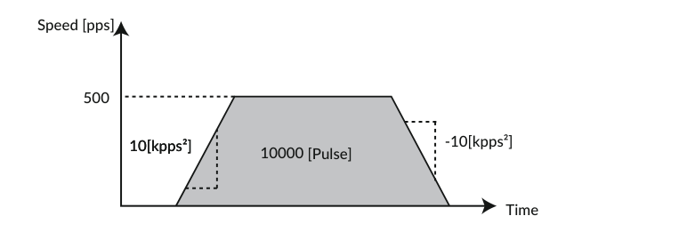
Confirmation format: send "CML command" Motion Data No. — the reply shows ".1" appended. Example: S2.1 → reply S2.1=50.
Motion mode (V command) options:
|
V |
Contents |
Detail |
|---|---|---|
|
0 |
PTP Motion |
Absolute positioning motion to the target position set by the P command with reference to the origin |
|
1 |
INC Motion |
Incremental positioning motion to move the distance set by the P command from the current position |
|
2 |
PTP Push Motion |
PTP Motion with the limited torque by Q command |
|
3 |
INC Push Motion |
INC Motion with the limited torque by Q command |
Continuous motion
When 10⁹ is set to the target position (P=1000000000), the motion will be continuous motion. For continuous motion the rotation direction is set only by the S command: regardless of the Coordinate Direction (K4) setting, a positive S value rotates the output shaft in the CW direction and a negative value in the CCW direction. Set a negative speed value only for continuous operation in the CCW direction.
After setting Motion Data and parameters, save them to the motor with the $ (Data Save) execution command. Make sure the motor is not running before sending the command.
Full command reference including all Motion Data commands (V/P/S/A/D/M/Q/ZL/ZH), execution commands ($, O, F) and query commands (?0–?1000): CM3 – CML (COOL MUSCLE Language).
Parameters that Shape I/O-Type Behavior
The following parameters are the ones most relevant to running an I/O Type system. Parameters marked "Restart" require a power cycle after saving before they take effect.
|
K |
Name |
Setting/Range |
Purpose |
|---|---|---|---|
|
K1 |
Resolution |
0–9 (300 to 12000 ppr) |
Pulse count per revolution. Restart required. |
|
K2 |
Speed Unit |
0: 100 pps / 1: 10 pps / 2: 1 pps |
Unit for the S command. Restart required. |
|
K4 |
Coordinate Direction |
0: Positive in CW / 1: Positive in CCW |
Coordinate direction. Restart required. |
|
K5 |
In-position Range |
1 – 500 pulse |
Range for In-position detection (see below). |
|
K6 |
Speed Override |
1 – 100 % |
Limits actual speed to the set proportion of S. |
|
K7–K10 |
Software Limit |
Enable/disable, boundaries, unit |
Restricts the motion range in software. |
|
K11 |
Push Motion Operation Mode |
0 – 3 |
Push torque direction and continuous/set-time mode. |
|
K13 |
Push Motion Holding Time |
1 – 30000 msec |
Time to continue Push Motion in set-time mode. |
|
K21 |
Origin Detection Execution |
0: Disable / 1: Enable |
Enables starting Origin Detection by input signal (assigns it to Motion Data 0 selection). |
|
K22 |
Origin Signal Source |
0 – 9 |
Origin Detection method (stopper / sensor / Z phase / Auto). Restart required. |
|
K23 |
Origin Detection Speed |
1 – 32767 (unit K2) |
Speed for Origin Detection. |
|
K24 |
Origin Detection Acceleration |
1 – 32767 kpps² |
Acceleration for Origin Detection. |
|
K25 |
Origin Detection Direction |
0: CW / 1: CCW |
Direction for Origin Detection. Restart required. |
|
K26 |
Origin Offset Distance |
±32767 pulse |
Offset from detected origin to coordinate origin. |
|
K27 |
Unit of Origin Offset Distance |
0: 100 / 1: 10 / 2: 1 pulse |
Unit for the offset. Restart required. |
|
K28 |
Stopper Detection Torque |
10 – 150 % |
Torque threshold to detect a stopper (% of rated torque). |
|
K29 |
Single Turn ABS Function |
0: Disabled / 1: Enabled |
Holds position within ±180° of origin after power off. Restart required. |
|
K30 |
Origin Detection Completion |
0: Disabled / 1: Enabled |
When enabled, no motion is accepted until Origin Detection is completed. Restart required. |
|
K42 |
Input Filter |
1 – 50 msec |
Filtering time for input signals. Restart required. |
|
K43 |
Input Logic |
6 digits, 0: Active High / 1: Active Low |
Input logic per input (IN1–IN6). Restart required. |
|
K44 |
Input 1 Function |
0: No Action / 1: Origin Sensor / 2: CCW Limit Sensor / 3: CW Limit Sensor |
Function assigned to Input 1 (Origin Sensor is available only for IN1). Restart required. |
|
K48 |
Input 5 Function |
0: No Action / 2: CCW Limit Sensor / 3: CW Limit Sensor |
Function assigned to Input 5. Restart required. |
|
K53 |
Output Logic |
3 digits, 0: Active High / 1: Active Low |
Output logic for OUT1–OUT3. Restart required. |
|
K54 |
Output Function |
0: ABZ Encoder Output / 1: User Defined |
Selects ABZ encoder output or user-defined functions for OUT1–3. Restart required. |
|
K55–K57 |
Output 1–3 Function |
0 – 10 |
Function assigned to each output when User Defined is selected (see Output Functions below). |
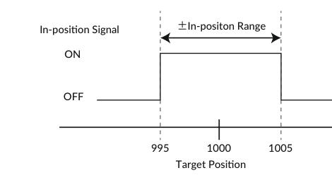
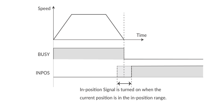
In-position (K5) — sets the range for In-position in the pulse unit. In-position is detected when the current position is within the set range against the target position. When stopping the motor by a stop command, the stopped position is recognized as the target position, so In-position is detected within the set range against the current position. When recognized as In-position, the In-position signal is ON and the motor status goes to Ux.1=8. Example: K5=5 — with a target position of 1000, In-position signals are sent out between 995 and 1005.
Full parameter descriptions with examples (Software Limit, Open Loop Holding, Single Turn ABS, Position Error Overflow, Overload Detection Time, Status Report): CM3 – Detail of Various Settings and CM3 – CML (COOL MUSCLE Language).
Wiring for I/O Control
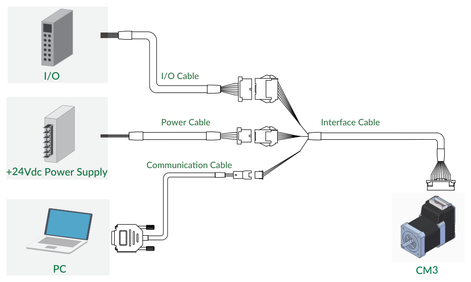
A typical I/O Type system connects an I/O controller (PLC etc.) through the I/O Cable, a +24Vdc power supply through the Power Cable, and a PC (for setup) through the Communication Cable.
Caution about cabling
Be sure that the power is off before plugging or unplugging connectors. Pay attention to straight insertion and removal of connectors by holding the connector's body. Be sure there is no stress on connectors. Be sure not to pull cables hard or hang CM3 by holding cables — it may result in damaging connectors.
Main Connector Pin Layout (I/O Type Functions)
CM3 has a 24-pin connector (55959-2430, Molex) on the top. The pin layout, names and I/O-Type functions are as follows.
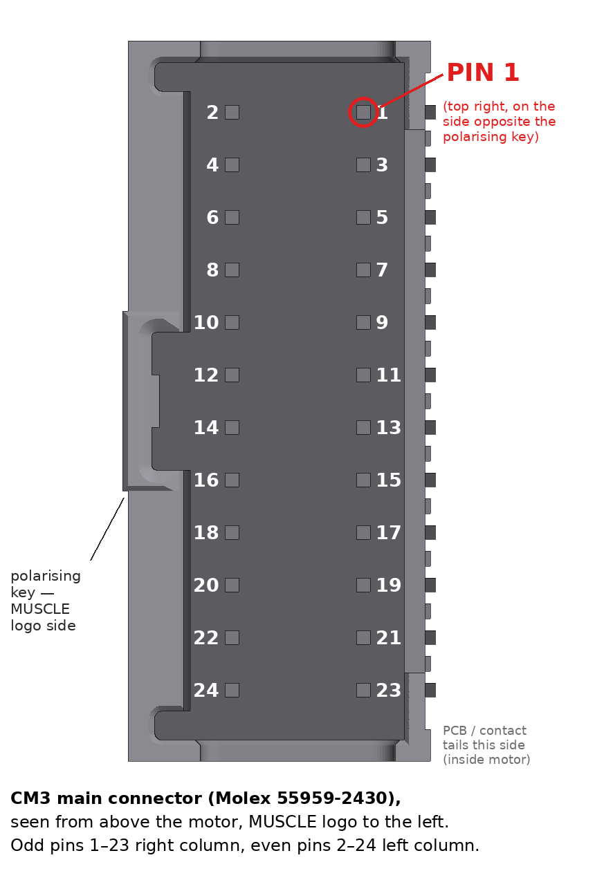
|
No. |
Name |
Function |
No. |
Name |
Function |
|---|---|---|---|---|---|
|
2 |
D_GND |
Digital Ground |
1 |
FG |
Frame Ground |
|
4 |
ALARM |
Alarm Output |
3 |
D_GND |
Digital Ground |
|
6 |
OUT3 |
Output 3 / Z-phase |
5 |
RXD0 |
RS232C Receive Data |
|
8 |
OUT2 |
Output 2 / B-phase |
7 |
TXD0 |
RS232C Transmit Data |
|
10 |
OUT1 |
Output 1 / A-phase |
9 |
STO_IN- |
STO Input - |
|
12 |
STO_IN+ |
STO Input + |
11 |
IN6+ |
Start・Stop |
|
14 |
IN6- |
Start・Stop |
13 |
IN5+ |
Limit Sensor |
|
16 |
IN5- |
Limit Sensor |
15 |
IN_COM |
IN1 to 4 Common |
|
18 |
IN4 |
Select Motion Data |
17 |
IN3 |
Select Motion Data |
|
20 |
IN2 |
Select Motion Data |
19 |
IN1 |
Origin/Limit Sensor |
|
22 |
P-GND |
Power Ground |
21 |
P-GND |
Power Ground |
|
24 |
POWER |
+24Vdc |
23 |
POWER |
+24Vdc |
I/O Cable
I/O Cable A (1000mm, 3000mm, 5000mm), Product Number CMIOA1-****S (****: cable length), wires AWG28 UL758 Style2464 (80℃ / 300V), XADRP-14V (JST) connector.
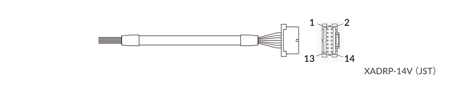
|
No. |
Name |
Function |
No. |
Name |
Function |
|---|---|---|---|---|---|
|
1 |
IN1 |
Origin/Limit Sensor |
2 |
IN2 |
Select Motion Data |
|
3 |
IN3 |
Select Motion Data |
4 |
IN4 |
Select Motion Data |
|
5 |
IN5+ |
Limit Sensor |
6 |
IN5- |
Limit Sensor |
|
7 |
IN6+ |
Start・Stop |
8 |
IN6- |
Start・Stop |
|
9 |
IN_COM |
Input 1 to 4 Common |
10 |
OUT1 |
Output 1 / A-phase |
|
11 |
OUT2 |
Output 2 / B-phase |
12 |
OUT3 |
Output 3 / Z-phase |
|
13 |
ALARM |
Alarm Output |
14 |
D_GND |
Digital Ground |
Wire color tables (two color schemes exist for this cable), Interface Cable, Communication Cable, Power Cable (CMPWA1) and the supplied varistor: CM3 – Wiring and Connection.
Electrical Specifications and Input/Output Circuits
|
Item |
Value |
|---|---|
|
Digital Input — Applied Voltage |
0 – 26 [V] |
|
Digital Input — Low Level Voltage |
0.8 [V] |
|
Digital Input — High Level Voltage |
4.2 [V] |
|
Digital Output — Withstanding Voltage |
26 [V] |
|
Digital Output — Max. Continuous Load Current |
10 [mA] |
Inputs IN1 to IN4 have no polarity (common terminal IN_COM); IN5 and IN6 have polarity (+/- terminals). Outputs OUT1–3 and ALARM are open-drain circuits.
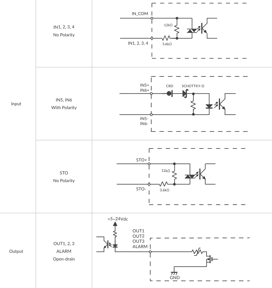
STO wiring
When not using the STO function, apply a voltage of 5 to 24V between STO+ and STO-.
Connection Examples
Connection example with a sink output circuit on the controller side:
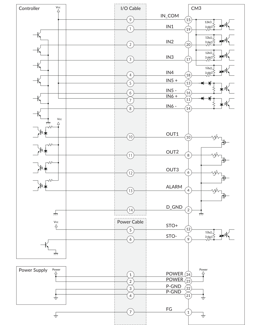
Connection example with a source output circuit on the controller side:
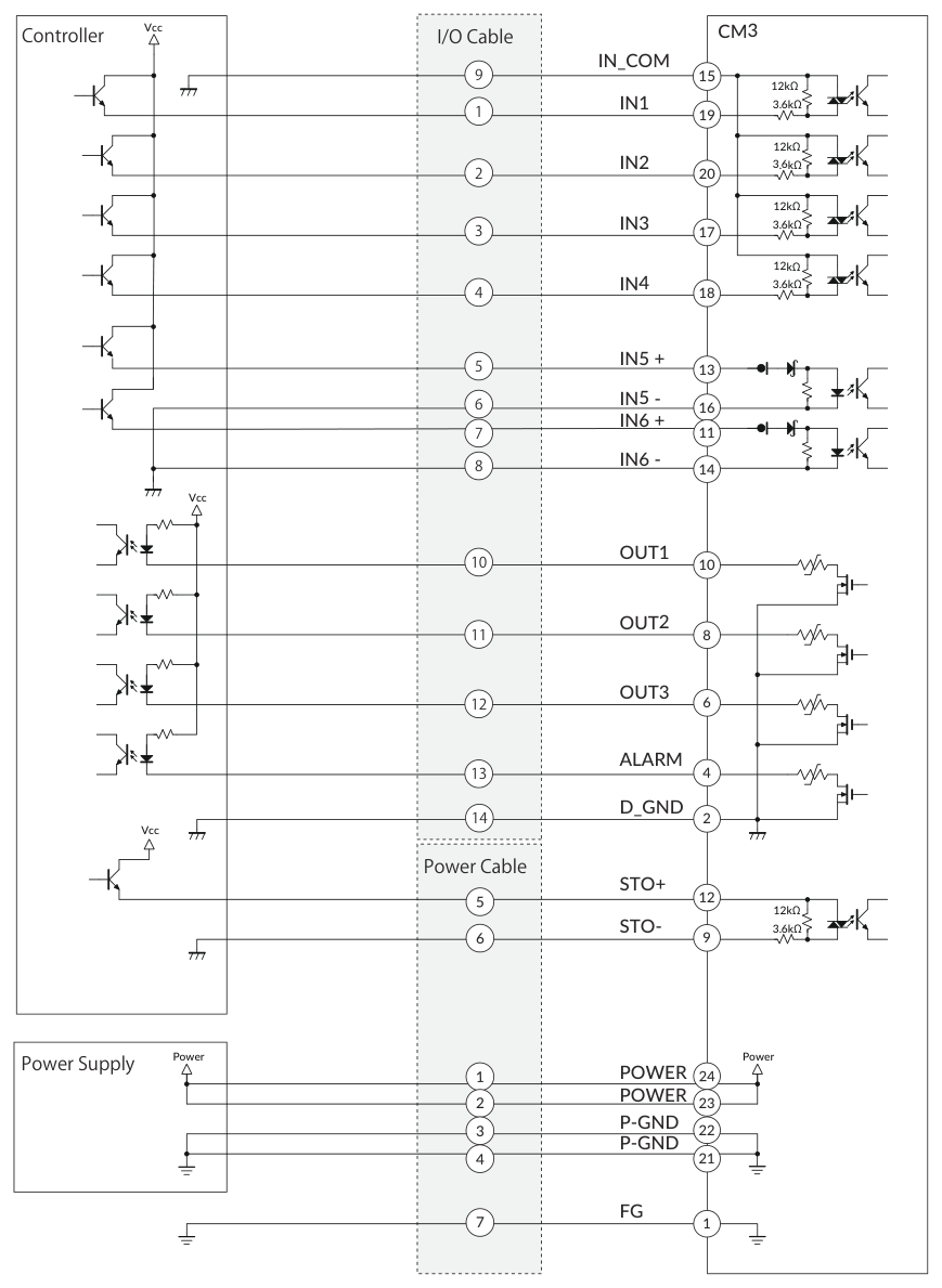
Warning
Make sure that the power is OFF while connecting the cables. Power ON after confirming the wiring is thoroughly correct. Make sure to ground the FG.
Operation
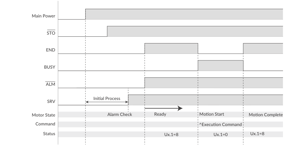
Sequence When Power is On
The sequence below describes from when the main power is turned on until CM3 is ready to accept the Start input signal. This sequence applies when the initial servo state is "Servo on". When the main power is turned on, the system checks that the STO function is off, then the servo is turned on. Next, the system checks the alarm status. When there is no alarm, the ALM and END outputs are turned off. Finally, CM3 is ready to accept the execution input signal.
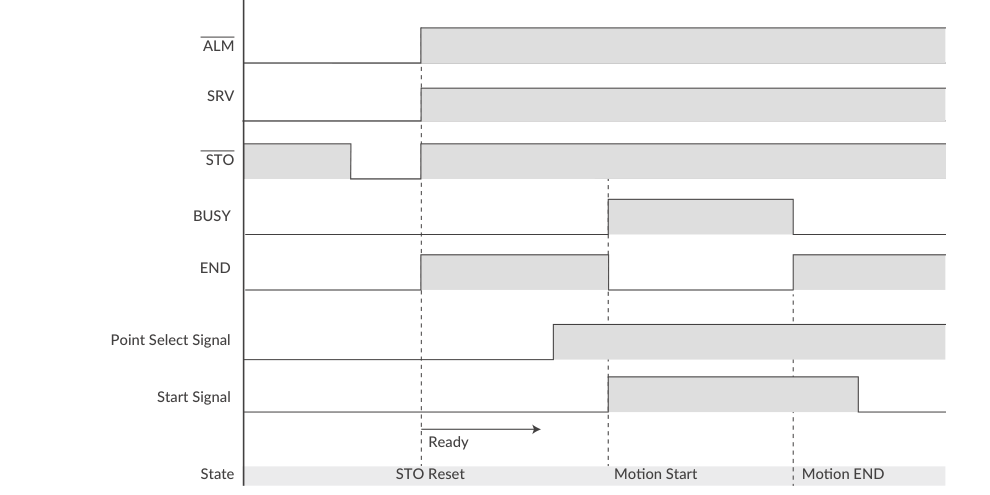
Sequence to Reset Alarm
An alarm is reset with the Point Select / Start signals as shown below. At the same time as the alarm is reset, the servo is turned on and CM3 is ready to accept the operation execution signal.
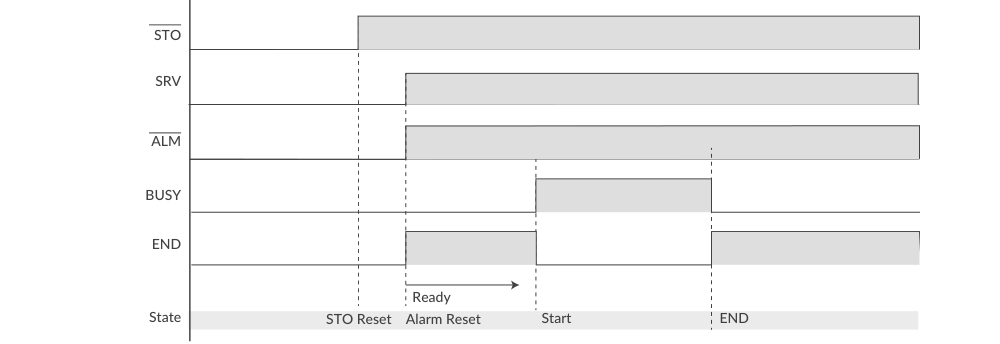
Servo On/Off — use the STO function to Servo on/off the I/O Type CM3 (turn the STO input voltage off and on). The recovery sequence from the STO state is shown below.
STO function detail and safety notes: CM3 – Various Functions.
Selecting Motion Data
CM3 reads the input status of IN2 to IN4 as a 3-bit binary code to select the Motion Data. OFF=0 and ON=1 are used for the calculation of the Motion Data number:
-
IN2: 2⁰ = 1
-
IN3: 2¹ = 2
-
IN4: 2² = 4
The Motion Data number is calculated by addition of the input status. Example: IN2 OFF, IN3 ON, IN4 ON → Selected Motion Data No. = 0(IN2) + 2(IN3) + 4(IN4) = 6.
|
Motion Data Number |
IN4 (Bit 2) |
IN3 (Bit 1) |
IN2 (Bit 0) |
|---|---|---|---|
|
0 |
OFF |
OFF |
OFF |
|
1 |
OFF |
OFF |
ON |
|
2 |
OFF |
ON |
OFF |
|
3 |
OFF |
ON |
ON |
|
4 |
ON |
OFF |
OFF |
|
5 |
ON |
OFF |
ON |
|
6 |
ON |
ON |
OFF |
|
7 |
ON |
ON |
ON |
The Motion Data No. is read as a binary code and executed by applying a signal to IN6 (Start).
PTP Motion / INC Motion Sequence
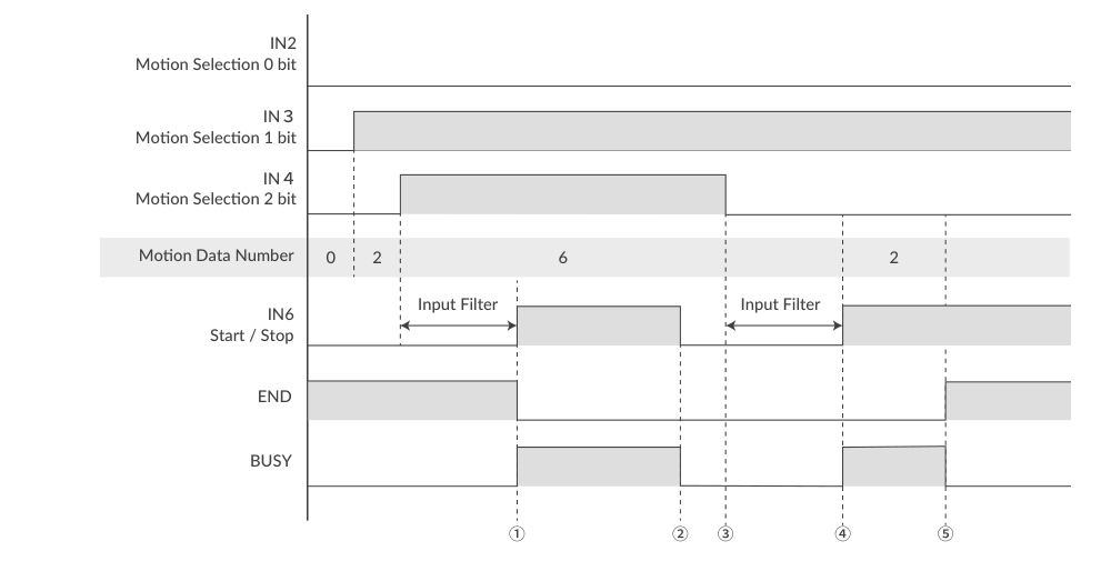
Set PTP Motion or INC Motion by the V command when setting the Motion Mode of each Motion Data. When performing PTP/INC Motion, refer to the following sequence. END Output and BUSY Output are valid only when they are set to an Output Function.
-
When selecting the Motion Data No., apply the signal to IN6 (Motion Execution signal) after the input filter time.
-
If IN6 is turned off (Motion Stop signal) before the motion is completed, the END output is not turned on because CM3 did not reach the target position.
-
Without END output, CM3 starts to read the binary code of the input status at the rising edge of the signal to IN6. In the sequence shown, Motion Data 6 is executed.
-
When changing the input state of IN6, change it after the input filter time.
-
When the motion is completed, the END output is turned on.
Start/Stop behavior
IN6 is both Start and Stop: a rising edge starts the selected Motion Data, and turning IN6 off before completion stops the motion. A stopped position is recognized as the target position for In-position detection.
Push Motion
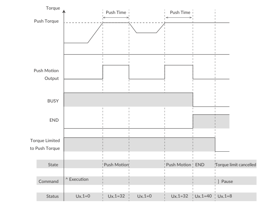
The Push Motion is an operation that limits the output torque to the set torque for the set time. It can be used for gripping and press-fitting workpieces. To execute Push Motion, set the Motion Mode (V command), Push Torque (Q command), Push Motion Operation Mode (K11), and Push Motion Holding Time (K13).
Push Motion is available by setting the Motion Mode to PTP Push Motion (V=2) or INC Push Motion (V=3):
-
PTP Push Motion: starts the Push Motion from the current position toward the set absolute position.
-
INC Push Motion: starts the Push Motion with the target position at the distance set from the current position.
In either case, set the target position so that it is several revolutions ahead of the object to be pushed. If the target position is too small, positioning may be completed before the workpiece is detected, or sufficient torque may not be generated.
Push Torque (Q command) — set the torque for Push Motion as a percentage of the rated torque (10–80%).
Push Motion Operation Mode (K11):
|
K11 |
Push Torque Direction |
Push Time |
|---|---|---|
|
0 |
One-direction |
Continuous |
|
1 |
One-direction |
Set time |
|
2 |
Both-direction |
Continuous |
|
3 |
Both-direction |
Set time |
-
One direction: the Push Torque is effective only in the operation direction — can be used to grip a rigid workpiece.
-
Both direction: the Push Torque is effective in both directions — can be used to grip an elastic workpiece or only detect a workpiece.
-
Continuous: regardless of the Push Motion Holding Time (K13), the Push Motion doesn't stop until the stop signal is given.
-
Set time: when the total push time reaches the Push Motion Holding Time (K13), the Push Motion is completed.
Example setup (values set over CWQ/CML, then executed by inputs):
K11=1        // Set Push Motion Operation Mode as One-direction and Set Time
K13=3000     // Set Push Motion Holding Time as 3000 msec
V2=2         // Set Motion Data 2 as PTP Push Motion
P2=10000     // Set Target Position 2 as 10000 pulses
S2=20        // Set Speed 2 as 20 (Unit: K2)
A2=50        // Set Acceleration 2 as 50 kpps2
Q2=30        // Set Push Torque 2 as 30% of Rated Torque
Input 3: ON  // Select Motion Data 2
Input 6: ON  // Start Motion Data 2
CM3 starts moving to the 10000 pulse position at the set acceleration and speed. CM3 goes into Push Motion when its torque reaches 30% of the rated torque and the status goes into Push Motion status (Ux.1=32). Push Motion is completed when the total Push Motion time reaches 3000 msec. After completion, the torque remains at the set Push Motion Torque and the status becomes Ux.1=40 (=32+8). The set torque remains until the Motion Stop signal (IN6 off) is given or the next Motion Data is executed.
Caution
If the object to be pushed cannot be detected during the Push Motion and the motor reaches the set target position, Ux.1=296 — the total of Operation Warning (256), Push Motion (32) and In-position (8) — is output. Sending the warning information query command ?199 returns the Push Motion Warning, WARN.1=1.
Origin Detection
Origin Detection can be selected from Stopper Detection, Origin Sensor, Z Phase Signal and their combinations with the Origin Signal Source parameter (K22):
|
K22 |
Content |
|---|---|
|
0 |
Stopper Detection |
|
1 |
Stopper Detection (Auto) |
|
2 |
Origin Sensor * |
|
3 |
Origin Sensor (Auto) * |
|
4 |
Stopper Detection + Z Phase Signal |
|
5 |
Stopper Detection + Z Phase Signal (Auto) |
|
6 |
Origin Sensor + Z Phase Signal * |
|
7 |
Origin Sensor + Z Phase Signal (Auto) * |
|
8 |
Z Phase Signal |
|
9 |
Z Phase Signal (Auto) |
* Valid only when the origin sensor is assigned to Input 1 (K44=1). "Auto" means Origin Detection starts automatically when the power is turned on.
Set the following parameters as needed to perform Origin Detection: motion (K21, K23, K24, K25), offset (K26, K27), Stopper Detection (K28), Origin Sensor (K44), completion (K30, K54, K55–K57 Origin Set Completion Output).
Starting Origin Detection by input signal (K21) — to start Origin Detection using the input signals, enable Origin Detection Execution (K21=1). Origin Detection is then assigned to the Motion Data 0 selection:
K21=1                  // Enable origin detection start
IN2 / IN3 / IN4: OFF   // Select Motion Data 0
IN6: ON                // Execute Origin Detection
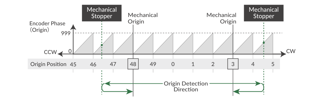
Stopper Detection — if the machine has a mechanical stopper, the origin search can use the stopper as the origin signal source. There are 50 origin positions (mechanical origins) per rotation; the encoder phase shifts from 0 to 999 linearly between each origin position. When Origin Detection is started, CM3 rotates in the set direction to detect the stopper. Stopper detection completes when the motor torque reaches the Stopper Detection Torque (K28) and the speed becomes 1/16 of the Origin Detection Speed; CM3 then displays the encoder phase information (Origin=0 to 999). After stopper detection, Origin Detection is completed at the encoder phase 0 point that is 1 cycle before the phase detected at the stopper. Phase 0 is not related to the Z phase.
-
When the Stopper Detection Torque is set too low, the origin is mis-detected because the torque threshold is reached early.
-
When Origin Offset is set, the position moved by the set offset distance from the detected mechanical origin becomes the coordinate origin.
-
For a stable origin search, adjust the attachment (e.g. coupling) so that the encoder phase value indicated in "Origin=***" is between 200 and 800.
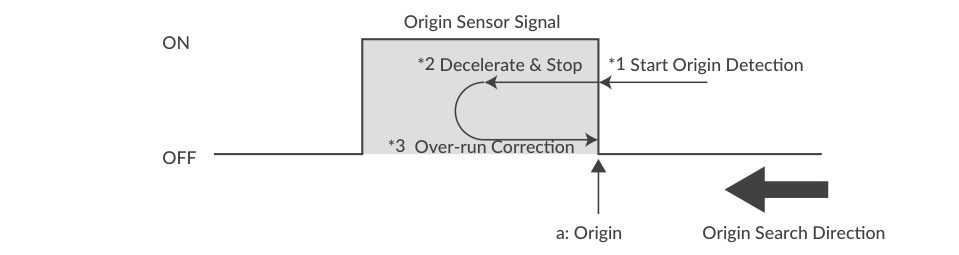
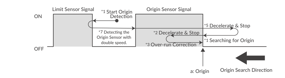
Origin Sensor — the origin sensor signal can be assigned only to IN1. The sensor detection circuit is a hysteresis circuit to minimize noise influence. The rising edge of the origin sensor in the Origin Detection Direction is detected as the mechanical origin. The motion differs depending on the sensor state when detection starts:
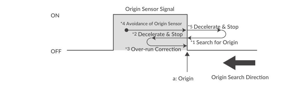
When a limit sensor and origin sensor are used simultaneously, CM3 reverses at twice the Origin Detection Speed when the limit sensor in the detection direction is hit, then finds the origin sensor:
Caution
If Origin Detection is executed when the origin sensor is not assigned to Input 1, Ux.1=264 (Operation Warning 256 + In-position 8) is output, and WARN.1=32 (operation warning) is returned to the query command ?199. When selecting the Input 1 function with K44, be sure to select the origin sensor (K44=1) or the limit sensor in the origin detection direction (K44=2: CCW limit sensor, K44=3: CW limit sensor).
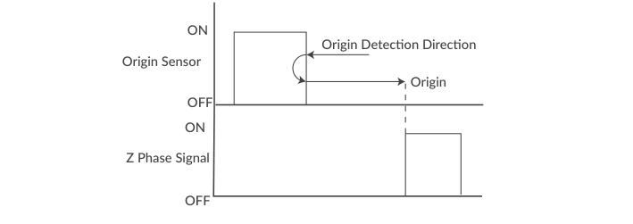
Z Phase Signal — the Z-phase signal is output once per rotation based on the internal encoder information. Origin Detection using Z-phase signals always finds the same origin within one rotation of the output shaft, so the sensor can be omitted in applications such as rotary tables. Origin Offset is ignored when using the Z Phase Signal. Combination with Stopper Detection / Origin Sensor is possible: after detecting an origin by Stopper Detection / Origin Sensor, CM3 moves in the opposite direction of the Origin Detection Direction and sets the first Z Phase Signal as the coordinate origin.
Origin Detection is shared with the Direct Type; further discussion: CM3 – Various Functions.
Input Functions
CM3 has 6 inputs. The functions of Input 1 and Input 5 are set with K44 and K48; the functions of inputs 2, 3, 4 and 6 are fixed.
|
Input |
Function |
Description |
|---|---|---|
|
1 |
Limit・Origin Sensor |
Select origin sensor (1) or CCW (2) / CW (3) limit sensor direction with K44 |
|
2 |
Motion Data Selection |
Select Motion Data by signal combination of IN2・IN3・IN4 |
|
3 |
Motion Data Selection |
Select Motion Data by signal combination of IN2・IN3・IN4 |
|
4 |
Motion Data Selection |
Select Motion Data by signal combination of IN2・IN3・IN4 |
|
5 |
Limit Sensor |
Select CCW (2) / CW (3) limit sensor direction with K48 |
|
6 |
Motion Execution / Stop |
Execute and stop the selected Motion Data |
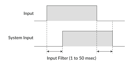
Input Filter — set the filter time for the input signals with K42 between 1 and 50 msec. The higher the number, the longer the filter time and the slower the response to the input. Signals shorter than the set value are not recognized as input signals. The filter by software cannot be removed. Example: K42=5 sets the filtering time to 5 msec.
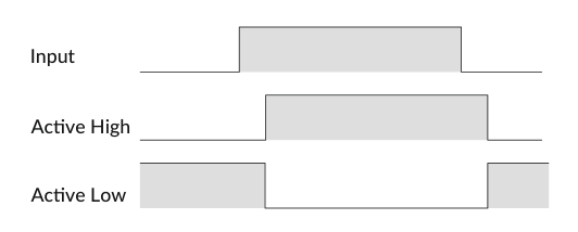
Input Logic — the input signal logic can be set per input with K43 (Active High / Active Low). Set it to suit the logic on the controller side.
Servo On/Servo Off — use the STO function to Servo on/off the I/O Type CM3 (see Sequence to Reset Alarm above).
Limit Sensor — the limit sensor function can be set for Input 1 and Input 5. Example: K44=2 (CCW limit sensor on Input 1), K48=3 (CW limit sensor on Input 5). When the limit sensor turns on, CM3 sends an Operation Warning (Ux.1=256) and the motor stops at the deceleration set in the Motion Data. The limit sensor warning (WARN.1=4) is returned with the warning information query command ?199. After stopping, CM3 can only move in the opposite direction of the limit sensor.
Output Functions
CM3 has 4 outputs. Functions can be assigned to Output 1–3; Output 4 is fixed to ALARM output. Either ABZ Encoder Output or User Defined can be selected for Output 1–3 with the Output Function parameter (K54). It is recommended to select ABZ Encoder Output when a host controller controls CM3, and User Defined when CM3 should output its status.
Alarm Output — assigned to Output 4. CM3 goes into Servo Off when an alarm occurs to protect CM3. Alarm information can be confirmed by the Status LED or by the reply to query command ?99. See "Sequence to Reset Alarm" above for cancelling an alarm.
ABZ Encoder Output — when K54=0, OUT1 to OUT3 are assigned to the ABZ phase encoder output. The Z phase is output once per rotation. The Resolution of the ABZ output is fixed at 3000 ppr when the Resolution parameter is set to 3000 ppr or higher; below 3000 ppr the ABZ output Resolution equals the Resolution parameter. Related parameters: Resolution (K1), Output Function (K54).
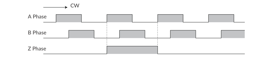
User Defined output functions — when K54=1, 3 of the following 11 functions can be assigned to Output 1 (K55), Output 2 (K56) and Output 3 (K57):
|
K55/K56/K57 |
Function |
Output Contents |
|---|---|---|
|
0 |
General Output |
Turn outputs on / off by command (O / F commands) |
|
1 |
In-position Output |
Output in the In-position range |
|
2 |
Warning Output |
Output in the Operation and Status Warning state |
|
3 |
Individual ZONE Output |
Output in the ZONE set by Motion Data (ZL/ZH) |
|
4 |
ZONE Output |
Output in the ZONE set by parameters (K59/K60) |
|
5 |
MOVE Output |
Output when speed exceeds MOVE Output Threshold (K58) |
|
6 |
BUSY Output |
Output during motion |
|
7 |
END Output |
Output when operation is completed |
|
8 |
Servo On |
Output when Servo On |
|
9 |
Push Motion Output |
Output when torque exceeds the set value during Push Motion |
|
10 |
Origin Set Completion Output |
Output when origin is set |
Positioning Status Output (In-position, BUSY, END) — CM3 goes into In-position status and outputs the signal from the output to which In-position Output is assigned when the current position enters the In-position range (±) set by K5. When END Output is assigned, the output turns on when the operation set in the Motion Data is completed. When the operation is paused (stopped before completion), the In-position Output turns on but the END Output does not.
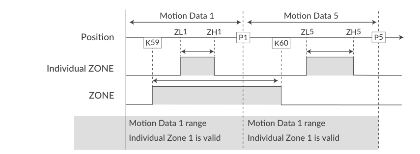
Individual ZONE / ZONE / MOVE Output — the Individual ZONE Output turns on when the current position is in the zone set by ZL/ZH of each Motion Data; it is valid from Motion Data execution until the next Motion Data positioning is executed. The ZONE Output turns on when the current position is in the zone set by ZONE(−) (K59) and ZONE(+) (K60) and is valid for all operation. The MOVE Output turns on when the speed exceeds the MOVE Output Threshold (K58). All output signals are valid only when the function is assigned to an output point.
Output Logic — when User Defined is selected, the logic of Output 1 to 3 can be switched with K53 (Active High: the gate in the open-drain circuit is ON when the output condition is true; Active Low: ON when the condition is false). Output 4 (Alarm output) is fixed as Active Low logic.
Monitoring from the host — the host can also poll status over RS-232C at any time: ?70 (input status), ?50 (output status), ?96 (current position), ?99 (motor status), ?199 (warning detail). Full query command list: CM3 – CML (COOL MUSCLE Language).
Worked Examples
Example 1: Three Motion Data Points from a PLC
This example sets up an origin search plus two motions, then runs them entirely from the digital inputs. All values are from the source manual examples.
1. Setup over CWQ/CML (once):
K21=1            // Enable Origin Detection start by input signal (uses Motion Data 0 selection)

V2.1=0           // Motion Data 2: PTP Motion
P2.1=10000       // Motion Data 2: target position 10000 pulse
S2.1=50          // Motion Data 2: speed 5000 pps (K2=0, 100 pps unit)
A2.1=10          // Motion Data 2: acceleration 10 kpps2
D2.1=100         // Motion Data 2: deceleration 100% of A

P6=1000000000    // Motion Data 6: continuous motion
S6=-100          // Motion Data 6: continuous speed 100 (unit K2) in the CCW direction

$                // Save all Parameters and Motion Data
2. Wire the selection inputs: connect PLC outputs to IN2, IN3, IN4 (selection), IN6 (Start/Stop) and IN_COM per the sink or source connection example above. If an origin or limit sensor is used, wire it to IN1 (K44) and/or IN5 (K48).
3. Operate from the PLC:
|
Step |
IN4 |
IN3 |
IN2 |
IN6 (Start/Stop) |
Result |
|---|---|---|---|---|---|
|
1 |
OFF |
OFF |
OFF |
ON |
Motion Data 0 selected → Origin Detection is executed (K21=1) |
|
2 |
OFF |
OFF |
OFF |
OFF |
Ready for the next selection (change inputs after the input filter time) |
|
3 |
OFF |
ON |
OFF |
ON |
Motion Data 2 selected → PTP Motion to 10000 pulse; END output turns on at completion |
|
4 |
OFF |
ON |
OFF |
OFF |
Ready for the next selection |
|
5 |
ON |
ON |
OFF |
ON |
Motion Data 6 selected (4+2=6) → continuous motion in the CCW direction |
|
6 |
ON |
ON |
OFF |
OFF |
Stop signal → motor decelerates and stops (END does not turn on; the stopped position becomes the target for In-position) |
Timing rule
Always change the IN2–IN4 selection code first, wait at least the input filter time (K42), then raise IN6. The selection code is latched at the rising edge of IN6.
Related Pages
-
CM3 – Functions and Structure — product codes, parts, rotating direction
-
CM3 – Installation — mounting to machinery and load
-
CM3 – Wiring and Connection — all cables, wire colors, varistor
-
CM3 – Input/Output — input filter, input/output logic and circuits
-
CM3 – Communication Functions — CWQ and terminal communication
-
CM3 – CML (COOL MUSCLE Language) — full parameter, Motion Data, execution and query command reference
-
CM3 – Detail of Various Settings — full parameter usage detail
-
CM3 – Various Functions — tuning, STO, streaming data, status LED
-
CM3 – Specifications — motor specifications, torque curves, dimensions