

This page is a self-contained handbook for the CM3 Pulse Type control mode: what it is, how to set it up, how to wire it, how to operate it, and a worked example. Material that also appears on the common pages is repeated here on purpose so that a Pulse Type user can work from this single page; italic cross-references point to the common pages with full detail.
What is the Pulse Type
The CM3 is an integrated AC servo system with a built-in encoder, driver and controller. The CM3 has three firmware-selectable control types — Direct, I/O and Pulse — and the control type is selected with the dedicated software COOL WORKS QUICK. On the Pulse Type, the CM3 operates by receiving pulse signals from a pulse generator such as a PLC or motion card: the host commands position by a pulse train, exactly as it would command a stepping motor, while the CM3 executes the motion with closed-loop servo control. The ABZ encoder output function allows you to replace a motor in an existing pulse-controlled system with the CM3.
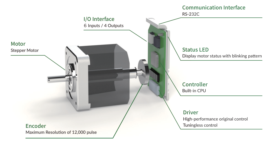
The pulse signal supports CW/CCW, Step/Direction, and A-phase/B-phase input methods, and the pulse input can be connected to either a line driver output or an open collector output on the host side. See Positioning by Pulse Input and Pulse Input Method (K41) below.
Main Functions (Pulse Type)
-
PTP Motion by Pulse Input Signal
-
Torque Limit Function
-
STO Function
-
Tuningless Function
-
ABZ-phase output and other output functions
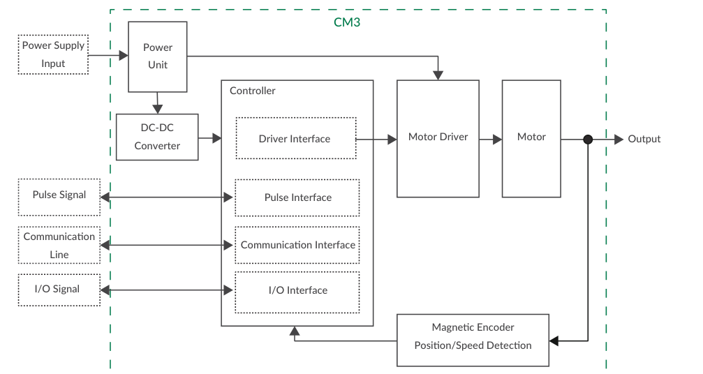
Function Block Diagram
Role of CML on the Pulse Type
CML (COOL MUSCLE Language) is used on the Pulse Type for setting up and checking the status of the CM3 over RS-232C; the motion itself is commanded by the pulse train. On the Pulse Type, CML consists of:
-
Parameters — set the system conditions such as communication settings, alarm conditions and so on.
-
Execution Commands — save data ($) and turn general outputs on/off (O, F).
-
Query Commands — read the CM3's current status such as current position and speed (?50 to ?199).
-
CM3 Status — current status (In-position, alarm, warning and so on) of the CM3.
Unlike the I/O and Direct Types, the Pulse Type has no Motion Data; positions, speeds and accelerations are determined entirely by the incoming pulse train.
Use 1-byte characters only. CML is not case sensitive. ".Motor ID" follows all CML replies but is not necessary when sending CML, as the CM3 is a single-axis controlled device.
Full CML reference including the command and query tables: CM3 – CML (COOL MUSCLE Language).
Setting Up
COOL WORKS QUICK (hereafter CWQ) is CML-compatible utility software with a user-friendly interface that assists easy operation of CM3. With CWQ, you can easily set and save parameters, stream data in graphs, and more. The latest version of CWQ and its manual are available for free on MUSCLE CORPORATION's website (https://musclecorp.com/motion-en).
The Pulse Type is the factory default control type, with Resolution 1000 ppr and CW/CCW pulse input. If these defaults suit your system, the CM3 can be operated by pulse signal straight away with no PC connection; the communication cable is only required when changing settings.
Establish Communication
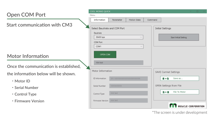
Connect the PC and CM3 with the communication cable. If the following information is displayed when powered on, communication between the PC and CM3 is established. If communication is not successful, please review the communication conditions.
When using host devices such as a PLC or HMI, or Windows terminal software such as Tera Term, the communication conditions must be set as follows.
|
Item |
Setting |
|---|---|
|
Baud rate |
38400 |
|
Data |
8 |
|
Parity |
NONE |
|
Stop |
1 |
|
Flow Control |
NONE |
Select Pulse Type in the Initial Setting Wizard
Once communication is established, select the control type from the initial setup wizard.
Step 1. Click the button below to open the Initial Setup Wizard.
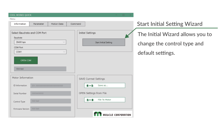
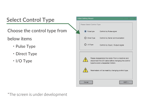
Step 2. When the Initialization Wizard opens, select a control type. Pulse Type is selected as the factory default; select Pulse Type if the motor is currently set to another control type.
Default Settings
The default settings for Resolution and pulse input method are as follows.
|
Item |
Default |
Values that can be set |
|---|---|---|
|
Resolution |
1000 ppr |
300 to 12000 ppr |
|
Pulse Input Method |
CW/CCW |
CW/CCW, Step/Direction, A-phase/B-phase |
-
When no change is required: Input the pulse signal from the controller and operate the motor.
-
When changing settings: Connect the PC and CM3, then change the settings following the steps below.
Change Basic Settings
After selecting the control type, select the Resolution and pulse input type.
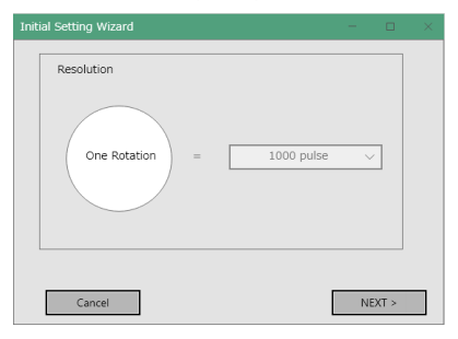
Resolution Setting
Select the number of pulses per revolution. Resolution can also be set by CML (K1). Full detail: Resolution (K1) on the Detail of Various Settings page.
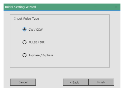
Pulse Input Type Setting
Select the pulse method to be input to CM3. See Pulse Input Method (K41) below for the timing of each method.
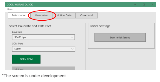
Other Settings
You can display all the setting items by clicking the Parameter tab shown below. The parameters that matter on the Pulse Type are summarised in Parameters that Shape Pulse-Type Behavior below.
Parameters that Shape Pulse-Type Behavior
Only the parameters below have an effect on the Pulse Type; Motion Data and the origin, software-limit and communication parameters of the I/O and Direct Types do not apply. Parameters marked Restart take effect after saving ($) and power-cycling. Set them from the CWQ Parameter tab or by CML (for example K41=1 followed by $).
|
K |
Name |
Setting / Range |
Restart |
What it does on the Pulse Type |
|---|---|---|---|---|
|
1 |
Resolution |
300 – 12000 ppr (K1=0…9; 2 = 1000 ppr) |
✓ |
Pulses per revolution. ABZ encoder output is capped at 3000 ppr. |
|
3 |
Servo ON/OFF Setting |
0: Servo Off, 1: Servo On |
|
State at power-on. With K3=0, turn Input 3 on to servo on. |
|
5 |
In-position Range |
1 – 500 pulse |
|
Range around the target in which In-position is reported. |
|
12 |
Torque Limit |
0 – 100 % |
|
Torque limit applied while Input 4 is on. See Torque Limit and Push Motion (Input 4) below. |
|
31 |
Tuning |
0: PPI, 1: Tuningless |
|
Tuning method. See Tuning below. |
|
32 |
Servo Stiffness |
30 – 150 |
|
Used when Tuningless (K31=1) is selected. |
|
33 / 34 / 35 |
Position P / Speed P / Speed I Gain |
1–5000 / 50–5000 / 0–5000 |
|
Used when PPI (K31=0) is selected. |
|
41 |
Pulse Input Method |
0: CW/CCW, 1: Step/Direction, 2: A Phase/B Phase |
✓ |
Must match the pulse generator. See Pulse Input Method (K41) below. |
|
42 |
Input Filter |
1 – 50 msec |
✓ |
Filter time for IN1–IN4. Not applied to the pulse inputs IN5/IN6. |
|
43 |
Input Logic |
6 digits, IN1…IN6: 0 Active High / 1 Active Low |
✓ |
Ex. IN1, IN3, IN5 Active Low: K43=010101 |
|
53 |
Output Logic |
3 digits, OUT1…OUT3: 0 Active High / 1 Active Low |
✓ |
Ex. OUT1 and OUT3 Active Low: K53=101 |
|
54 |
Output Function |
0: ABZ Encoder Output, 1: User Defined |
✓ |
Selects what OUT1–OUT3 carry. See Output Functions below. |
|
55 / 56 / 57 |
Output 1 / 2 / 3 Function |
0 General, 1 In-position, 2 Warning, 5 MOVE, 8 Servo On, 9 Torque Limit |
|
Used when K54=1. (3, 4, 6, 7, 10 are not available on the Pulse Type.) |
|
58 |
MOVE Output Threshold |
0 – 2147483648 pps |
|
Speed above which the MOVE Output turns on. |
|
61 / 62 |
Temperature / Load Warning Threshold |
0 – 100 ℃ / 0 – 100 % |
|
Thresholds for the Warning Output. |
|
63 |
Position Error Overflow Threshold |
1 – 32767 (×1000 pulse) |
|
Position error at which the overflow alarm is raised. Relevant when pushing (Input 4). |
|
64 |
Overload Detection Time |
100 – 10000 msec |
|
Time at overload before the Overload alarm. |
|
65 |
Status LED |
0: Enabled, 1: Disabled |
|
See Status LED below. |
|
66 |
Status Report |
Bit field B0–B5 |
|
Automatic reports to the host (In-position/Alarm, input/output status, warnings…). |
Full parameter table with ranges, defaults and the Applies-to column: CM3 – CML (COOL MUSCLE Language). Setting details for K1, K5, K63, K64 and K66: CM3 – Detail of Various Settings.
Pulse Input Method (K41)
The following pulse input methods are available for CM3. Select the method with K41 to match the pulse generator (a restart is required for the change to take effect).
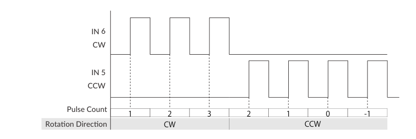
CW/CCW (K41=0)
Pulses on IN6 rotate the motor in the CW direction; pulses on IN5 rotate it in the CCW direction.
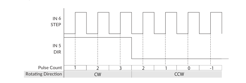
Step/Direction (K41=1)
Pulses on IN6 (STEP) command the travel; the level on IN5 (DIR) selects the rotating direction.
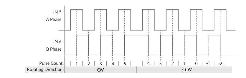
A Phase/B Phase (K41=2)
Quadrature pulses on IN5 (A phase) and IN6 (B phase) command travel and direction; the count changes on each edge.
Wiring for Pulse Control
Typical Connection Example
Be sure that the power is off before plugging or unplugging connectors. Pay attention to straight insertion and removal of connectors by holding the connector's body. Be sure there is no stress on connectors, and do not pull cables hard or hang the CM3 by its cables — it may result in damaging the connectors.
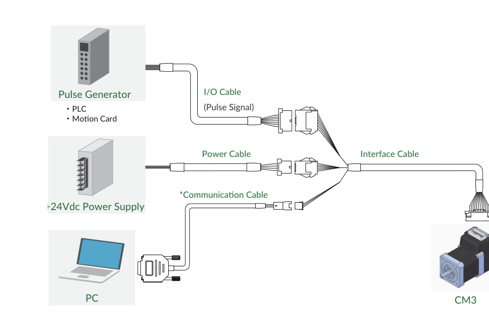
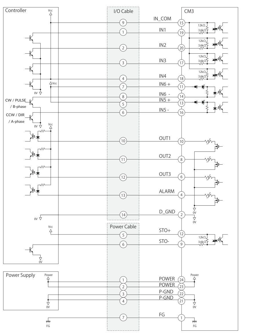
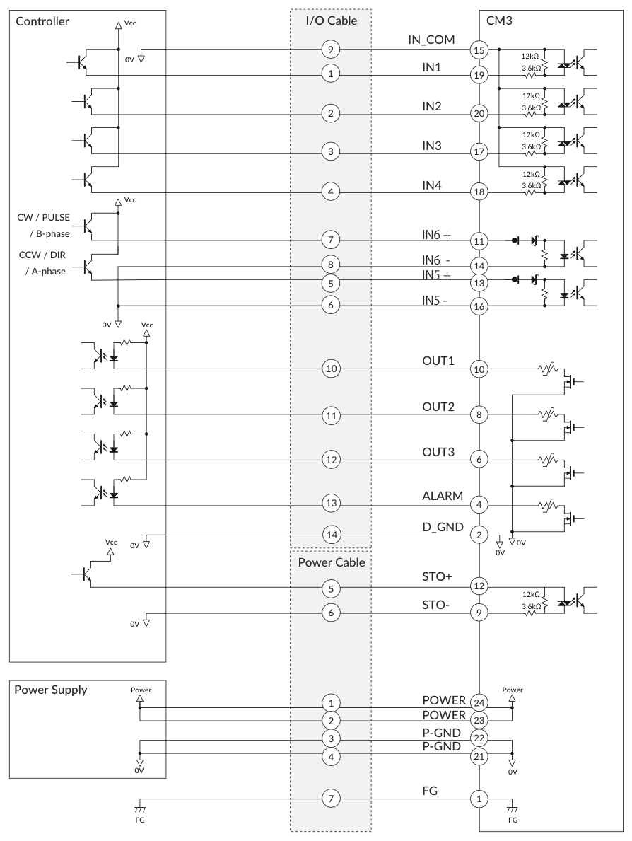
The pulse generator (PLC or motion card) connects through the I/O cable, which carries the pulse signal. The communication cable to a PC is required only when changing the CM3 settings.
Main Connector Pin Functions (Pulse Type)
CM3 has a 24-pin connector (55959-2430, Molex) on the top. On the Pulse Type, the pin functions are as follows. Note that IN5 and IN6 are the differential pulse inputs.
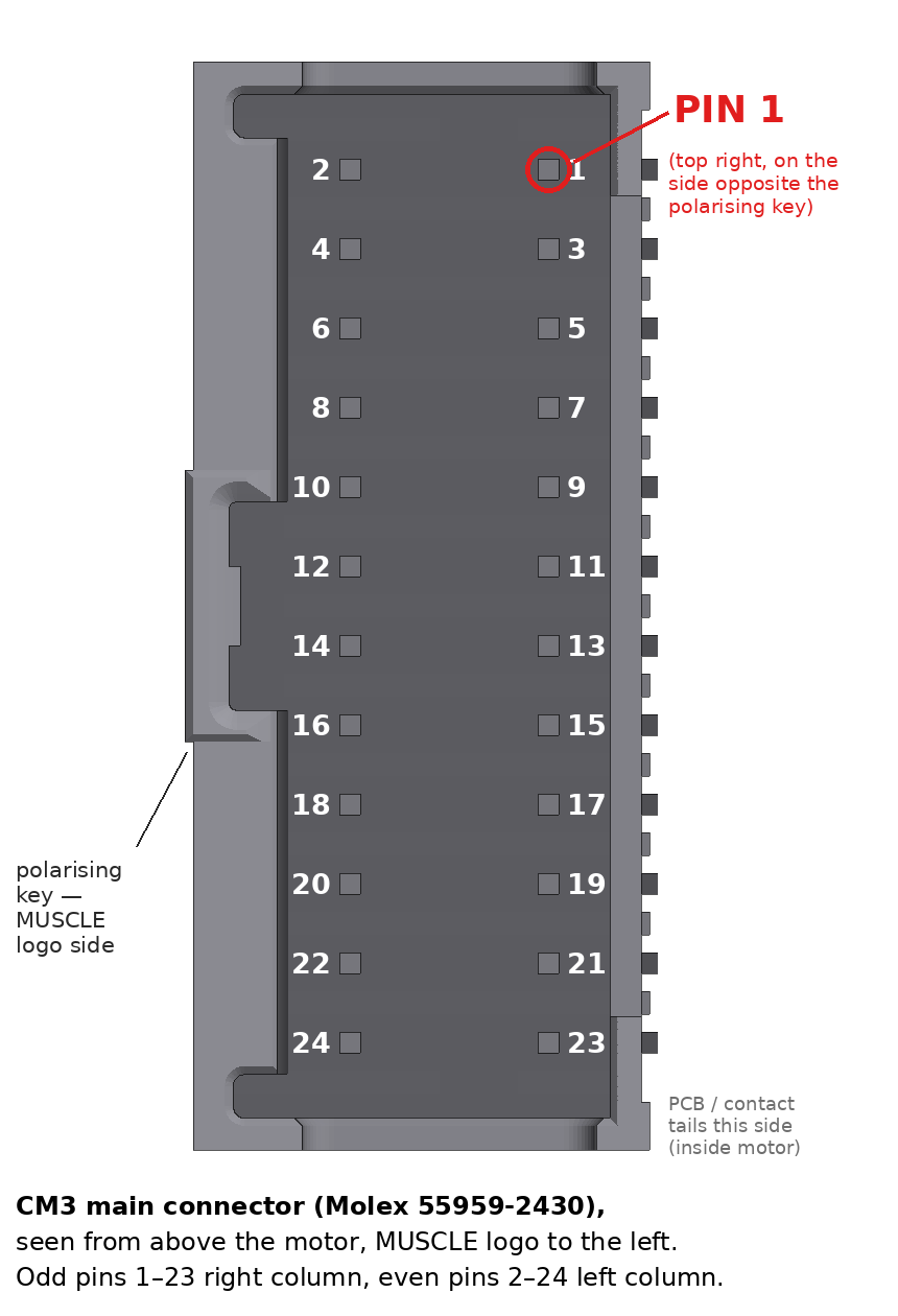
|
No. |
Name |
Function |
|---|---|---|
|
1 |
FG |
Frame Ground |
|
2 |
D_GND |
Digital Ground |
|
3 |
D_GND |
Digital Ground |
|
4 |
ALARM |
Alarm Output |
|
5 |
RXD0 |
RS232C Receive Data |
|
6 |
OUT3 |
Output 3 / Z-phase |
|
7 |
TXD0 |
RS232C Transmit Data |
|
8 |
OUT2 |
Output 2 / B-phase |
|
9 |
STO_IN- |
STO Input - |
|
10 |
OUT1 |
Output 1 / A-phase |
|
11 |
IN6+ |
CW / Step / B-Phase Pulse + |
|
12 |
STO_IN+ |
STO Input + |
|
13 |
IN5+ |
CCW / Dir / A-Phase Pulse + |
|
14 |
IN6- |
CW / Step / B-Phase Pulse - |
|
15 |
IN_COM |
IN1 to 4 Common |
|
16 |
IN5- |
CCW / Dir / A-Phase Pulse - |
|
17 |
IN3 |
Servo on/off |
|
18 |
IN4 |
Torque Limit |
|
19 |
IN1 |
CCW Limit Sensor |
|
20 |
IN2 |
CW Limit Sensor |
|
21 |
P-GND |
Power Ground |
|
22 |
P-GND |
Power Ground |
|
23 |
POWER |
+24Vdc |
|
24 |
POWER |
+24Vdc |
The available cables are Interface Cable A (CMIFA1), Communication Cable A (CMRSA1), I/O Cable A (CMIOA1) and Power Cable A (CMPWA1). Cable drawings, connector types and wire color tables: CM3 – Wiring and Connection.
Electrical Specifications of the Signals
|
Item |
|
Value |
|---|---|---|
|
Digital Input |
Applied Voltage |
0 - 26 [V] |
|
Digital Input |
Low Level Voltage |
0.8 [V] |
|
Digital Input |
High Level Voltage |
4.2 [V] |
|
Pulse Input |
Max. Input Pulse Frequency |
1 [MHz] |
|
Pulse Input |
Duty |
50 ± 10% |
|
Digital Output |
Withstanding Voltage |
26 [V] |
|
Digital Output |
Max. Continuous Load Current |
10 [mA] |
Input/Output Circuit
CM3 is equipped with 4 digital inputs with no polarity (IN1 to IN4), 2 pulse signal inputs with polarity (IN5 and IN6), the STO input, and 4 open-drain outputs (OUT1 to OUT3 and ALARM).
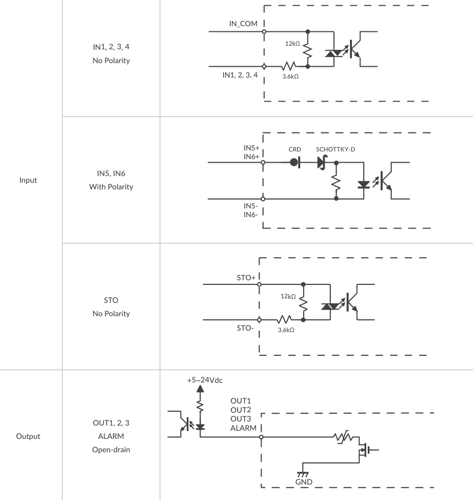
When not using the STO function, apply a voltage of 5 to 24V between STO+ and STO-.
Pulse Input Circuit
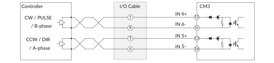
CM3 supports line driver output or open collector output pulse signals. Input pulse maximum frequency: 1 [MHz].
Line Driver Output
Open Collector Output
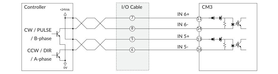
Connection Example with Sink Output Circuit
Connection Example with Source Output Circuit
Make sure that the power is OFF while connecting the cables. Power ON after confirming the wiring is thoroughly correct.
Make sure to ground the FG.
Operation
The legend below applies to the sequence diagrams in this section.
-
INPOS: In-position (Ux=8)
-
ALM: Alarm output (Ux=Alarm No.)
-
STO: STO (Ux=1024)
-
SRV: Servo status (Ux=16)
Sequence When Power is On
The sequence below describes from when the main power is turned on until CM3 is ready to accept the pulse signal. This sequence is only for the initial servo state "servo on" (K3=1).
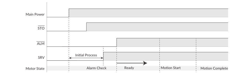
When the main power is turned on, the system checks that the STO function is off, then the servo is on. Next, the system checks the alarm status. When there is no alarm, the alarm output is turned off and CM3 is ready for operation by pulse signal.
Positioning by Pulse Input
Positioning is performed point-to-point by the pulse train applied to IN5/IN6: each input pulse moves the motor one Resolution step, and the rotating direction is determined by the selected pulse input method. The timing diagrams for the three pulse input methods (CW/CCW, Step/Direction, A Phase/B Phase) are shown in Pulse Input Method (K41) above. The maximum input pulse frequency is 1 MHz with a duty of 50 ± 10%.
Servo On / Servo Off and Alarm Reset (Input 3)
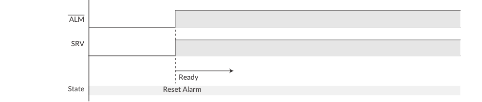
CM3 can be set to Servo On (Alarm Reset) / Servo Off by turning Input 3 on/off with a signal. When Input 3 is on, Reset Alarm and Servo On are executed at the same time and CM3 sends the state Ux.1=8 (In-position). When Input 3 is off, CM3 sends the state Ux.1=16 (Servo Off).
In case of an alarm status, remove the cause of the alarm, then Servo On / Reset Alarm by a signal to Input 3. When an alarm is reset, CM3 becomes servo on and operation by pulse signal is possible.
Limit Sensors (Inputs 1 and 2)
The limit sensor functions are fixed to Input 1 (CCW Limit Sensor) and Input 2 (CW Limit Sensor). When a limit sensor is on, an Operation Warning (Ux.1=256) is sent, then CM3 slows down and stops. A Limit Sensor Warning (WARN.1=4) is replied to the Query command ?199. After stopping by a limit sensor, operation is possible only in the opposite direction to the limit sensor.
Torque Limit and Push Motion (Input 4)
By turning on Input 4, the torque limiting function is enabled. During torque limitation, the maximum torque is limited to the torque set by K12 and the Torque Limit Output is turned on (the Torque Limit Output is available only when the output function is assigned). Turning Input 4 off removes the maximum torque limit.
Push Motion by Torque Limit
CM3 can continuously push or grip an object with this function. Turn on Input 4 to limit the output torque to the value set by K12, and drive the motor against the object with the pulse input; the limitation is off when Input 4 is off.
Apply the pulse signal so as not to overflow the Position Error Overflow Threshold (K63) when using this function. When disabling this function, send the pulse signal in the opposite direction and make sure that CM3 has moved away from the object.
Input Functions Summary
|
Input |
Function |
Description |
|---|---|---|
|
1 |
CCW Limit Sensor |
Stop CM3 from moving in the CCW direction. |
|
2 |
CW Limit Sensor |
Stop CM3 from moving in the CW direction. |
|
3 |
Servo On/Alarm Reset |
Turn Servo On/Off. Alarm will be reset after Servo On. |
|
4 |
Torque Limit On/Off |
Limit the maximum torque at the value set by K12. |
|
5 (±) |
Pulse input |
CCW / Dir / A-Phase pulse input (with polarity, no input filter). |
|
6 (±) |
Pulse input |
CW / Step / B-Phase pulse input (with polarity, no input filter). |
The filter time for Inputs 1 to 4 is set with K42 (1 to 50 msec); signals shorter than the set value are not recognized as input signals. The input filter cannot be used for the pulse inputs. The input logic of each input can be set with K43.
Output Functions
CM3 has 4 outputs. Functions can be assigned to Outputs 1 to 3, while Output 4 is fixed to ALARM output. Either ABZ Encoder Output or User Defined can be selected for Outputs 1 to 3 with K54. It is recommended to select ABZ Encoder Output when a host controller controls CM3, and User Defined when CM3 should output its status.
Alarm Output
The alarm output function is assigned to Output 4. CM3 goes into Servo Off when an alarm occurs, to protect CM3. Alarm information can be confirmed by the Status LED or by the reply to the Query command ?99. Output 4 (Alarm output) is fixed as Active Low logic.
ABZ Encoder Output
When the output function is set to "ABZ Encoder Output" (K54=0), OUT1 to OUT3 are assigned to the ABZ phase encoder output function. The Z phase is output once per rotation, and the relationship between the AB phases and the Z phase is as follows.
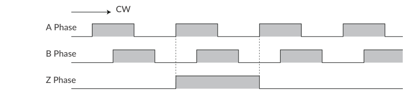
Related parameters: Resolution (K1), Output Function (K54). The Resolution of the ABZ output is fixed at 3000 ppr when the Resolution parameter is set to 3000 ppr or higher. If the Resolution parameter is less than 3000 ppr, the Resolution of the ABZ encoder output will be the same as the Resolution parameter.
User Defined Output Functions
By selecting "User Defined" for the output function (K54=1), the following functions can be assigned to Outputs 1, 2 and 3. Select the function of Output 1 with K55, Output 2 with K56, and Output 3 with K57.
|
K55/K56/K57 |
Function |
Output Contents |
|---|---|---|
|
0 |
General Output |
Turn outputs on / off by command (O / F) |
|
1 |
In-position Output |
Output in the In-position range |
|
2 |
Warning Output |
Output in the Operation and Status Warning state |
|
3, 4 |
N/A |
N/A |
|
5 |
MOVE Output |
Output when speed exceeds the MOVE Output Threshold (K58) |
|
6, 7 |
N/A |
N/A |
|
8 |
Servo On |
Output when Servo On |
|
9 |
Torque Limit Output |
Output when Torque Limit is active by a signal to Input 4 |
|
10 |
N/A |
N/A |
Positioning Status Output (In-position): CM3 goes into In-position status and outputs a signal from the Output that In-position Output is assigned to, when the current position goes into the In-position range (±) set by the In-position Range parameter (K5). The In-position signal is turned off when the deviation between the input pulse and the current position is greater than the In-position range.
MOVE Output: The output turns on when the speed set by the MOVE Output Threshold (K58) is exceeded. This output signal can be used as an operating signal.
All output signals are valid only when the output function is assigned to outputs.
Tuning
The servo tuning method can be selected from Tuningless or PPI control with the Tuning parameter (K31).
-
Tuningless (K31=1): CM3 is automatically optimized for changes of load, motion and so on, from the low to high speed range. When some adjustment of trackability is necessary, it can be adjusted by the Servo Stiffness parameter (K32, 30 to 150). The higher the Servo Stiffness value, the higher the trackability, but setting it too high will cause motor vibration.
-
PPI (K31=0): for a fixed load and operation. Adjust in this order: set the initial values (K33=100, K34=150, K35=1), then optimize Speed P Gain (K34), then Position P Gain (K33), then Speed I Gain (K35), operating the motor mounted in the machine to find the optimum values. Even gain values select Constant Gain Mode; odd values select Variable Gain Mode.
Full step-by-step gain adjustment with the gain-versus-speed diagrams: CM3 – Various Functions.
STO Function
CM3 is equipped with the STO (Safe Torque Off) function defined in IEC61800-5-2, which cuts off only the power supply to the motor. If a voltage is applied between STO+ and STO-, STO does not function and CM3 is ready to operate. When the voltage is cut off, STO works and issues the STO status (Ux=1024); the motor's stopped state is not controlled and the servo is turned off. When the voltage is applied again, STO is canceled, the alarm is canceled, and the servo is turned on at the same time. STO and recovery sequence diagrams: CM3 – Various Functions.
Status LED
The status of CM3 is indicated by the status LED in 7 colors (blue, green, red, magenta, cyan, yellow, white) with lighting, flashing and alternating patterns — for example STO, alarms (overload, over current, over temperature, over voltage, low voltage, position error overflow), servo on/off, limit sensor, warnings, and Torque Limit each have their own pattern. If multiple statuses occur at the same time, the higher-priority status is shown. The LED can be disabled with K65. Full blinking pattern table: CM3 – Various Functions.
Worked Examples
Example 1: Two Revolutions by Step/Direction from a PLC
Goal: a PLC with open-collector pulse outputs turns the motor exactly two revolutions clockwise, then the PLC confirms the move is complete.
-
Select the control type. Connect the PC with the communication cable, open CWQ, run the Initial Setup Wizard and choose Pulse Type (see Setting Up above).
-
Set resolution and pulse method. On the Change Basic Settings page choose 1000 ppr and Step/Direction, or send
K1=2,K41=1and$. Both parameters need a restart, so power-cycle the CM3. -
Wire the pulse inputs. Connect the PLC STEP output to IN6 and the DIR output to IN5 as shown in Open Collector Output and Connection Example with Sink Output Circuit above; connect the servo-on signal to Input 3 and +24 V / P-GND to the power pins.
-
Servo on. Power on. With the default K3=1 the CM3 reports Ux.1=8 (In-position) once it is ready; if K3=0, turn Input 3 on first (see Sequence When Power is On above).
-
Move. Hold DIR at the level for CW rotation (see Step/Direction (K41=1)) and output 2000 STEP pulses, for example at 20 kpps. At 1000 ppr this is two revolutions, and 20 kpps corresponds to 1200 rpm, so the move takes about 0.1 s. Stay below the 1 MHz maximum input frequency with a 50 ± 10 % duty.
-
Confirm. Assign In-position to an output (K54=1, K55=1) and let the PLC wait for OUT1, or poll the status with the query commands on the CML (COOL MUSCLE Language) page. If the move is short by a few pulses, check the Input Filter (K42 does not apply to IN5/IN6) and the pulse edge/duty from the PLC.
To push against a stop instead of positioning, limit the torque first (K12) and turn Input 4 on before the pulses — see Torque Limit and Push Motion (Input 4) above.