

Input Signal
Input Filter
CM3 has 6 inputs in total: 4 digital inputs (IN1 to IN4) that do not come with polarity, and 2 digital inputs (IN5 and IN6) with polarity. A filter function (1 to 50 msec) by software is available on all inputs. The filter function by software cannot be removed. The minimum filtering time is 1 msec and the detection sequence is shown in the diagram below.
Pulse Type
On the Pulse Type, IN5 and IN6 are pulse signal inputs with polarity (CM3 is equipped with 4 digital inputs with no polarity, IN1 to IN4, and 2 pulse signal inputs with polarity, IN5 and IN6, totaling 6 points). The software filter function (1 to 50 msec) applies to Input 1 to Input 4 only. The input filter function cannot be used for the pulse inputs.
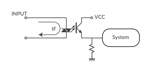
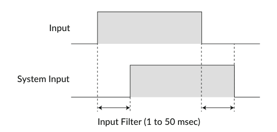
When Input Filter is set, a signal shorter than the set time is not detected as a signal.
Input Logic
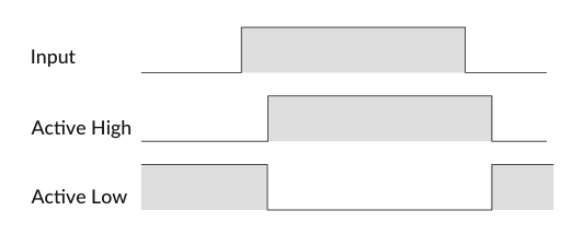
Input signal logic can be set by a parameter. Active High and Active Low settings are as shown in the diagram below. Set it to suit the logic on the controller side.
Output Signal
Output Function
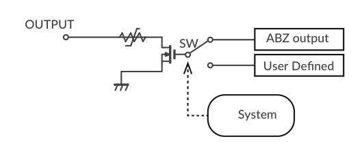
CM3 has 4 outputs that are an open-drain circuit. OUT4 is fixed for Alarm Output, and the other outputs (OUT1 to OUT3) can be set as ABZ Output or General Output by parameters.
Output Logic
When selecting "User Defined" by the Output Function parameter, the logic for Output 1 to Output 3 can be switched.
Pulse Type
The logic for Output 1 to Output 3 can be switched by setting a parameter.
* Output 4 (Alarm output) is fixed as Active Low logic.
-
Active High: Gate in open-drain circuit is ON when output condition is true
-
Active Low: Gate in open-drain circuit is ON when output condition is false
Refer to Output Functions on the Various Functions page for further information.