

This page is a self-contained handbook for the CM3 Direct Type control mode: what it is, how to set it up, how to wire it, how to operate it by CML commands, and worked examples. Material that also appears on the common pages is repeated here on purpose so that a Direct Type user can work from this single page; italic cross-references point to the common pages with full detail.
What is the Direct Type
Direct Type (communication type) lets you operate CM3 by sending and receiving commands via RS-232C serial communication from a host controller such as a PC, PLC, HMI or microcomputer. Positioning can be done by simple settings such as position, speed and acceleration. Up to 32 point Motion Data can be set and executed.
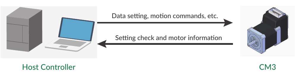
Direct Type CM3 is controlled by RS-232C serial communication. After setting A (Acceleration), S (Speed) and P (Position), motion is executed by the execution command ^.
S=10       //Set speed as 10
A=5        //Set acceleration as 5
P=1000     //Set target position as 1000
^          //Execution
A maximum of 32 Motion Data can be created. Each Motion Data is composed of the items needed for a motion, such as speed, acceleration and target position. Motion starts when an execution command is sent after setting data in the specified Motion Data.
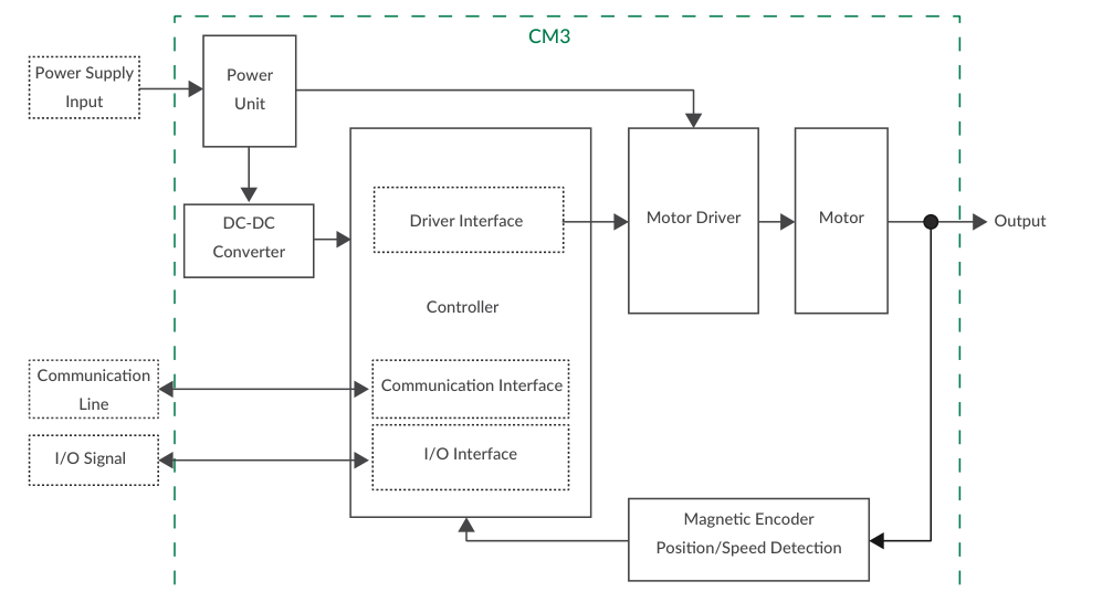
COOL MUSCLE Language (CML)
CML (COOL MUSCLE Language) is the programming language used to operate and control CM3. It consists of:
-
Parameters — set the system conditions such as communication settings and alarm conditions (K commands).
-
Motion Data — set the motion conditions from the current position to the target position (V, P, S, A, D, M, Q, ZL, ZH commands, data numbers 0 to 31).
-
Execution Commands — commands that execute preset content in CM3 (
^,],[,|,$and others). -
Query Commands — read CM3's current status such as position and speed (
?commands). -
CM3 Status — the current status (In-position, alarm, warning, etc.) reported by CM3.
CML basics
Use 1-byte characters only. CML is not case sensitive. Separate CML data commands with CR or CRLF (delimiters are omitted in the examples on this page). ".Motor ID" follows all CML, but since CM3 is a single-axis controlled device it is not necessary when sending CML to CM3; ".Motor ID" (".1") is however added in the replied data.
Setting Up
Connecting to a PC and Communication Conditions
CM3 sends and receives commands to and from host devices such as PC, PLC and HMI via RS-232C serial communication. Connect the PC with Communication Cable A (CMRSA1). There are two ways to communicate:
-
The dedicated software, COOL WORKS QUICK
-
Terminal software on Windows such as Tera Term
For host devices (PLC, HMI) and Windows terminal software, set the communication conditions as follows:
|
Item |
Setting |
|---|---|
|
Baud rate |
38400 |
|
Data |
8 |
|
Parity |
NONE |
|
Stop |
1 |
|
Flow Control |
NONE |
With a terminal, you simply type CML commands (e.g. ?99, S=10, ^) followed by Enter, and CM3 replies in the formats shown in the CML quick reference below.
COOL WORKS QUICK (CWQ)
COOL WORKS QUICK (CWQ) is CML-compatible utility software with a user-friendly interface that assists easy operation of CM3. With CWQ you can easily set and save parameters and data, stream data in a graph, and more. The latest version of CWQ and its manual are available for free on MUSCLE CORPORATION's website (https://musclecorp.com/motion-en).
If the following information is displayed when powered on, communication between PC and CM3 is established. If communication does not succeed, review the communication conditions.
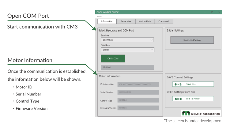
Select Direct Type in the Initial Setting Wizard
Once communication is established, select the control type from the Initial Setting Wizard.
Step 1. Click the button below to open the Initial Setting Wizard.
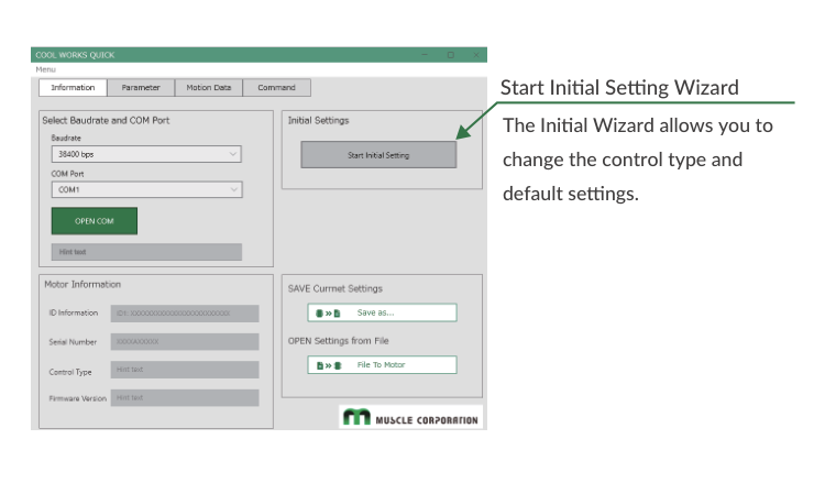
Step 2. When the Initialization Wizard opens, select the control type. The Pulse Type is selected as the factory default; for the operation described on this page, select "Direct Type".
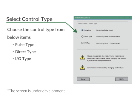
Full setup details: CM3 – Communication Functions.
Communication Parameters (K71, K72, K73)
The serial link itself is configured by the communication parameters below. When the Baud Rate (K71) is changed, the host baud rate needs to be changed to match.
|
K |
Name |
Setting / Range |
Unit |
Restart |
Remarks |
|---|---|---|---|---|---|
|
71 |
Baud Rate |
0: 38.4 / 1: 9.6 / 2: 19.2 / 3: 57.6 / 4: 115.2 |
kbps |
|
Set the baud rate. |
|
72 |
Parity |
0: None / 1: Even / 2: Odd |
– |
|
Set the parity when transferring data. |
|
73 |
Delimiter |
0: CR / 1: CRLF |
– |
|
Set the delimiter type at the end of replied data from CM3. |
K71=1 //Set 9.6 kbps as the baud rate.
Caution
The set baud rate might not be available on some PCs and host instruments. Please enter a proper value that matches their specifications.
Caution
CM3's communication buffer could be overflowed by a delay of communication data processing when a lot of data are transferred to CM3 and over-written; unexpected motion is then possibly produced.
CML Quick Reference
Parameter Setting and Confirmation
Parameters set the operating environment such as Resolution, communication settings and protection functions.
-
Setting format:
K[Parameter Number]=[Value] -
Confirmation format:
K[Parameter Number]
//Setting example: Software Limit 10000 pulse (+) and enable the function
K10=100      // *The pulse unit of the Software Limit is 100 pulses
K7=1

//Confirming example: check whether the Software Limit function is valid
K7           //Send to CM3
K7.1=1       //Sent from CM3 to host
-
Please change parameters while CM3 is stopped.
-
The changed parameter value is saved by executing the Data Save command (
$). Unless the Data Save command is executed, the previously saved value will remain when the power is turned on again. -
For safety reasons, there are some settings that require a power off and on (Restart).
Full parameter list (all types): CM3 – CML (COOL MUSCLE Language); function details: CM3 – Detail of Various Settings.
Motion Data
Up to 32 Motion Data can be set, numbered 0 to 31. Each Motion Data consists of the items below (setting format: [CML command][Motion Data No.]=[Value]).
|
Command |
No. |
Name |
Setting / Range |
Unit |
|---|---|---|---|---|
|
V |
0 - 31 |
Motion Mode |
0: PTP Motion / 1: INC Motion / 2: PTP Push Motion / 3: INC Push Motion |
– |
|
P |
0 - 31 |
Position Data |
Depends on Resolution |
pulse |
|
S |
0 - 31 |
Speed Data |
± 200000 |
Set by K2 |
|
A |
0 - 31 |
Acceleration |
1 - 32767 |
kpps² |
|
D |
0 - 31 |
Deceleration Ratio |
1 - 150 |
% of A command |
|
M |
0 - 31 |
Torque Limit |
0 - 100 |
% of Max. Torque |
|
Q |
0 - 31 |
Push Motion Torque |
10 - 80 |
% of Rated Torque |
|
ZL |
0 - 31 |
Individual ZONE(―) |
Depends on Resolution |
pulse |
|
ZH |
0 - 31 |
Individual ZONE(+) |
Depends on Resolution |
pulse |
-
Position: one pulse is the unit angle of positioning; pulses per rotation is the Resolution (default 1000 ppr, settable 300 to 12000 ppr by parameter K1). When 10⁹ is set to the target position (
P=1000000000), the motion becomes continuous motion; the rotation direction is then set only by the sign of the S command (positive = CW, negative = CCW, regardless of K4). -
Speed: unit is selected from 100 pps, 10 pps or 1 pps by parameter K2. Conversion: Speed[rpm] = S Data × Speed Unit [pps] × 60 [sec/min] / Resolution [ppr]. Example: S=100, K2=0 (100 pps), Resolution 1000 ppr → 600 rpm.
-
Acceleration: unit of A data is kpps² (1000 pps²). Example: S=500, K2=0, A=100 → acceleration time = 500 × 100 / (100 × 1000) = 0.5 sec.
Setting example — set 10000 pulse Position, 5000 pps Speed and 10 kpps² Acceleration in Motion Data 2:
V2=0          //Set PTP Motion to Motion Type of Motion Data 2
P2=10000      //Set 10000 pulse to Position of Motion Data 2
S2=50         //Set 5000 pps to Speed of Motion Data 2 (Unit set by K2)
A2=10         //Set 10 kpps² to Acceleration of Motion Data 2
D2=100        //Set 100% to Deceleration of Motion Data 2
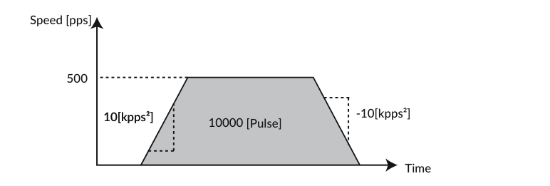
Confirmation format: send the command with the Motion Data number, e.g. S2.1 — CM3 replies S2.1=50 (".1" is displayed in replied data).
Execution Commands (Full Direct Type Set)
Execution commands trigger actions on CM3 such as executing/stopping motion and cancelling alarms. By using execution commands and Query commands together, a sequence operation can be created on the host side.
Execution format: [CML command][No] — the number can be omitted when it is not required. Example: ^28 executes Motion Data 28.
|
CML |
Name |
No |
Contents |
|---|---|---|---|
|
^ |
Motion Data Execution |
0 - 31 |
Execute the Motion Data of the specified No. |
|
] |
Stop・Cancel Alarm |
– |
|
|
[ |
Restart |
– |
Resume paused motion. |
|
| |
Origin Detection |
– |
Start Origin Detection (set by K21 to K30). |
|
|1 |
Move to Position 0 |
– |
Move to position 0. |
|
|2 |
Reset Current Position |
– |
Reset the current position to 0. |
|
$ |
Data Save |
– |
Save data. *Make sure the motor is not running before sending the command. |
|
) |
Servo OFF |
– |
Servo off. |
|
(0 |
Servo ON |
– |
Servo on (available only after alarm reset). The number can be omitted: |
|
(1 |
Alarm Reset |
– |
Reset an alarm. |
|
# |
Teaching |
0 - 31 |
Capture current position to the specified position memory (available only during Manual Mode). |
|
O |
Output Signal On |
1 - 3 |
Turn on the specified output. |
|
F |
Output Signal Off |
1 - 3 |
Turn off the specified output. |
Query Commands
Query commands read the set data and current status of CM3.
|
CML |
Name |
Unit |
Replied contents |
|---|---|---|---|
|
?0 - ?31 |
Motion Data |
N/A |
Display the specified Motion Data. |
|
?50 |
Output Status |
N/A |
|
|
?70 |
Input Status |
N/A |
|
|
?71 |
Temperature in Driver Case |
℃ |
|
|
?72 |
Power Voltage |
0.1 V |
|
|
?79 |
Load Factor |
% |
|
|
?85 |
Version Information |
N/A |
Display CM3 version information. |
|
?90 |
List of Parameters |
N/A |
Display the list of all K parameters. |
|
?95 |
Position Deviation |
Pulse |
|
|
?96 |
Current Position |
Pulse |
|
|
?97 |
Current Speed |
Set by K2 |
|
|
?98 |
Current Torque |
% |
|
|
?99 |
Motor Status |
N/A |
|
|
?199 |
Warning |
N/A |
|
|
?1000 |
List of Motion Data |
N/A |
Display the list of all Motion Data. |
Motor Status (?99, Reply Format Ux.1=[decimal])
|
Value |
Name |
Detail |
Classification |
|---|---|---|---|
|
0 |
Moving |
Motor is running or out of in-position range. |
– |
|
1 |
Position Error Overflow |
Alarm occurs when position deviation exceeds the K63 setting. |
Alarm |
|
2 |
Overvoltage Alarm |
Alarm occurs when input voltage exceeds 30 V. |
Alarm |
|
4 |
Overload Alarm |
Alarm occurs when the current torque exceeds the maximum torque for the time set by K64. |
Alarm |
|
8 |
In-position |
When in in-position range with servo on. |
– |
|
16 |
Servo off |
Servo-off. |
– |
|
32 |
Push Motion |
Push Motion. |
– |
|
64 |
Overcurrent Alarm |
Alarm occurs when excessive current such as regenerative current flows. |
Alarm |
|
128 |
Temperature Alarm |
Alarm occurs when internal temperature exceeds 110 ℃. |
Alarm |
|
256 |
Operation Warning |
Inoperable condition; check the detail with ?199. |
Warning |
|
512 |
Low Voltage Alarm |
Alarm occurs when main power supply falls below 18 V. |
Alarm |
|
1024 |
STO Activated |
STO signal is turned off. |
Alarm |
|
2048 |
Status Warning |
Temperature or load factor threshold exceeded; check the detail with ?199. |
Warning |
|
4096 |
ABS Alarm |
When origin detection has not been completed after setting the Single Turn ABS function (K29) to enable. |
Alarm |
Statuses are additive: e.g. Ux.1=40 = Push Motion (32) + In-position (8). When an alarm occurs, the Ux corresponding to the alarm is issued, the alarm output is turned on and the servo is turned off. Remove the cause of the alarm before cancelling the alarm.
Warning (?199, Reply Format WARN.1=[hex])
|
Bit |
Name |
Detail |
Classification |
|---|---|---|---|
|
B0 |
Push Motion Warning |
Reached the target position during Push Motion. |
Operation Warning |
|
B1 |
Software Limit Warning |
Execution command to a target position set over the software limit is sent. |
Operation Warning |
|
B2 |
Limit Sensor Warning |
Limit sensor is on. |
Operation Warning |
|
B3 |
Manual Mode Warning |
Execution command is sent in Manual Mode. |
Operation Warning |
|
B4 |
Origin Detection Incomplete Warning |
An execution command was sent while origin detection was not completed and Origin Detection Completion (K30) was enabled. |
Operation Warning |
|
B5 |
Execution Warning |
An operation command is sent when operation cannot be performed. |
Operation Warning |
|
B6 |
Temperature Warning |
Temperature inside the driver case exceeds the set value of K61. |
Status Warning |
|
B7 |
Over Load Warning |
The load exceeds the set value of K62. |
Status Warning |
The motor axis does not servo off in a warning state. To reset an Operation Warning, send the pause command ].
Full union command tables for all control types: CM3 – CML (COOL MUSCLE Language).
Wiring for Direct Control
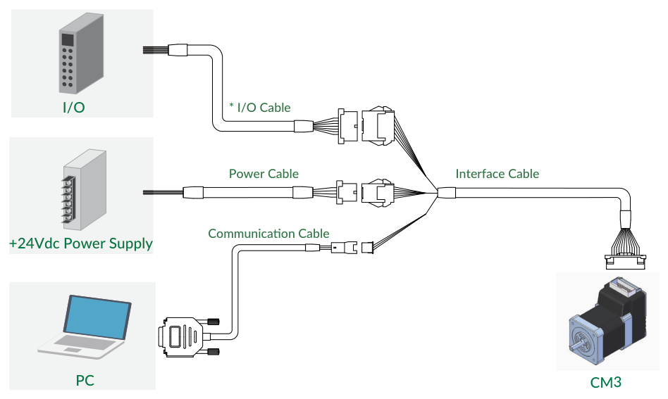
The I/O Cable is required only when the I/O (input/output) function is used in addition to command control from the host.
Caution about cabling
Be sure that the power is off before plugging or unplugging connectors. Pay attention to straight insertion and removal of connectors by holding the connector's body. Be sure there is no stress on connectors, and do not pull cables hard or hang CM3 by its cables — it may result in damaging connectors.
Main Connector Pin Functions (Direct Type)
CM3 has a 24-pin connector (55959-2430, Molex) on the top. Pin functions in Direct Type are:
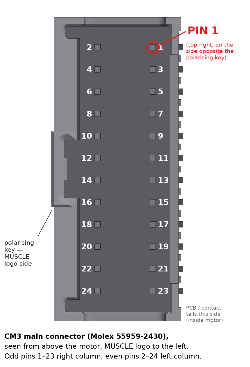
|
No. |
Name |
Function |
No. |
Name |
Function |
|---|---|---|---|---|---|
|
1 |
FG |
Frame Ground |
2 |
D_GND |
Digital Ground |
|
3 |
D_GND |
Digital Ground |
4 |
ALARM |
Alarm Output |
|
5 |
RXD0 |
RS232C Receive Data |
6 |
OUT3 |
Output 3 / Z-phase |
|
7 |
TXD0 |
RS232C Transmit Data |
8 |
OUT2 |
Output 2 / B-phase |
|
9 |
STO_IN- |
STO Input - |
10 |
OUT1 |
Output 1 / A-phase |
|
11 |
IN6+ |
CW Inching・Jog |
12 |
STO_IN+ |
STO Input + |
|
13 |
IN5+ |
CCW Inching・Jog |
14 |
IN6- |
CW Inching・Jog |
|
15 |
IN_COM |
IN1 to 4 Common |
16 |
IN5- |
CCW Inching・Jog |
|
17 |
IN3 |
Servo on・off |
18 |
IN4 |
Manual Mode |
|
19 |
IN1 |
Origin/Limit Sensor |
20 |
IN2 |
Limit Sensor |
|
21 |
P-GND |
Power Ground |
22 |
P-GND |
Power Ground |
|
23 |
POWER |
+24Vdc |
24 |
POWER |
+24Vdc |
Cables
-
Interface Cable A — CMIFA1-****WR (400, 1000, 2000, 3000, 5000 mm). Breaks the main connector out to the power, communication and I/O cables.
-
Communication Cable A — CMRSA1-****W (1000, 2000, 3000, 5000 mm), D-sub 9 (XM3D-0921, Omron) to XARR-03VF (JST).
-
I/O Cable A — CMIOA1-****S (1000, 3000, 5000 mm).
-
Power Cable A — CMPWA1-****S (1000, 3000, 5000 mm).

|
Side |
Color |
No. |
Name |
Function |
|---|---|---|---|---|
|
PC side |
GRY |
2 |
RXD |
RS232C Transmit Data from PC |
|
PC side |
ORG |
3 |
TXD |
RS232C Receive Data from PC |
|
PC side |
WHT |
5 |
D_GND |
Digital Ground |
|
CM3 side |
ORG |
1 |
RXD |
RS232C Receive Data from CM3 |
|
CM3 side |
GRY |
2 |
TXD |
RS232C Transmit Data from CM3 |
|
CM3 side |
WHT |
3 |
D_GND |
Digital Ground |
Input/Output Circuits and Electrical Specifications
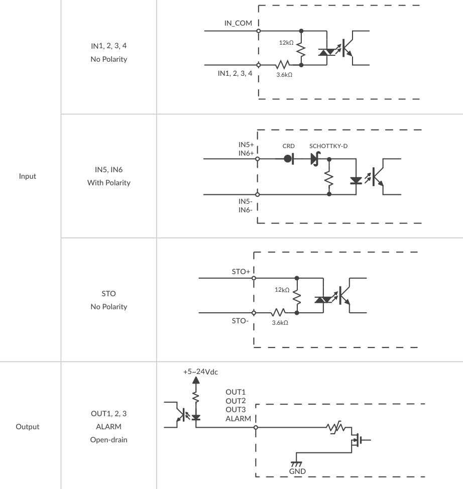
IN1 to IN4 have no polarity (common: IN_COM); IN5 and IN6 have polarity (+/- pins). Outputs OUT1 to OUT3 and ALARM are open-drain. When not using the STO function, apply a voltage of 5 to 24 V between STO+ and STO-.
|
Item |
|
Value |
|---|---|---|
|
Digital Input |
Applied Voltage |
0 - 26 [V] |
|
Digital Input |
Low Level Voltage |
0.8 [V] |
|
Digital Input |
High Level Voltage |
4.2 [V] |
|
Digital Output |
Withstanding Voltage |
26 [V] |
|
Digital Output |
Max. Continuous Load Current |
10 [mA] |
Warning
Make sure that the power is OFF while connecting the cables. Power ON only after confirming the wiring is thoroughly correct. Make sure to ground the FG.
Sink/source connection examples, the supplied valistor and full cable pin-out tables: CM3 – Wiring and Connection.
Operation
Legend for the sequence diagrams in this section: INPOS = In-position (Ux.1=8), ALM = Alarm output (Ux.1=Alarm No.), BUSY = During operation (Ux.1=0), STO = STO (Ux.1=1024), SRV = Servo status (Ux.1=16) — accessible via communication or output signal; END = End (output signal only).
Sequence When Power is On
The sequence below runs from when the main power is turned on until CM3 is ready to accept commands. This sequence applies when the initial servo state is "Servo on" (K3=1).
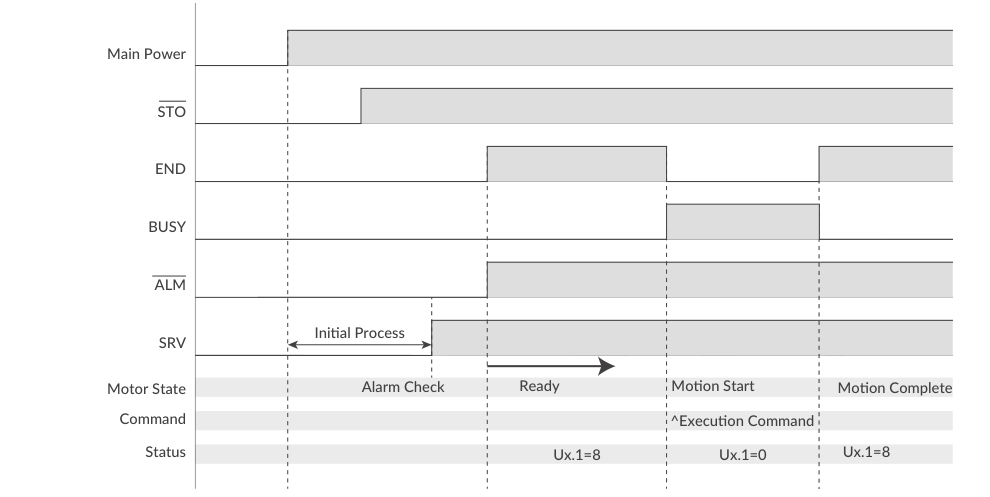
When the main power is turned on, the system checks that the STO function is off, then the servo turns on. Next, the system checks the alarm status. When there are no alarms, the ALM and END outputs are turned off. Finally, CM3 is ready to accept execution commands.
Sequence to Reset an Alarm
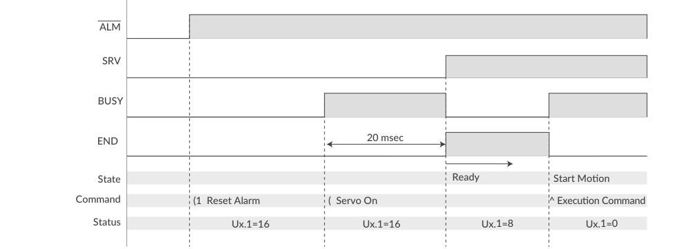
In case of an alarm status, remove the cause of the alarm and reset the alarm with (1. Then send the Servo On command ( after alarm reset and checking the status. 20 msec after Servo On, CM3 will be ready to accept execution commands.
External brake
If using an external brake, release the brake within this 20 msec.
Positioning by Commands
Motion Data is composed of the elements necessary for operation, such as speed, acceleration, target position and torque. Motion Data can be registered and saved in CM3, and positioning is performed by specifying the Motion Data number with the execution command ^. Absolute positioning (PTP Motion), relative positioning (INC Motion) and push motion are available. (PTP Motion means PTP (ABS directive); INC Motion means PTP (INC directive).)
PTP Motion example — set the data below to Motion Data 1 and execute:
V1=0       //Set PTP Motion to Motion Mode
P1=10000   //Set 10000 pulse to Position
S1=100     //Set 100 (Unit: K2) to Speed
A1=100     //Set 100 kpps² to Acceleration
^1         //Execute Motion Data 1
INC Motion example:
V1=1       //Set INC Motion to Motion Mode
P1=10000   //Set 10000 pulse to position
S1=100     //Set 100 (Unit: K2) to Speed
A1=100     //Set 100 kpps² to Acceleration
^1         //Execute Motion Data 1
When the positioning is completed, CM3 sends the status Ux.1=8 indicating in-position.
Pause, Resume and Stop during Motion
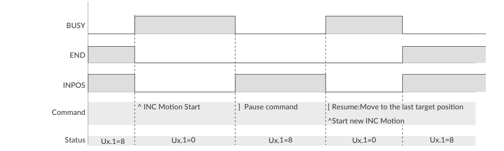
When the Pause command ] is sent during INC Motion, CM3 stops and In-position is detected. With the Restart command [, CM3 goes to the former target position and the motion is completed.
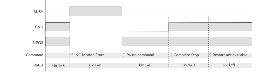
Sending the Pause command ] again while paused makes CM3 a complete stop (END status); it will not move even if the Restart command is sent.
Push Motion by Commands
Push Motion limits the output torque to the set torque for the set time. It can be used for gripping and press-fitting workpieces. To execute Push Motion, set the Motion Mode (V=2: PTP Push Motion, V=3: INC Push Motion), Push Torque (Q command, % of rated torque), Push Motion Operation Mode (K11) and Push Motion Holding Time (K13).
|
K11 |
Push Torque Direction |
Push Time |
|---|---|---|
|
0 |
One-direction |
Continuous |
|
1 |
One-direction |
Set time |
|
2 |
Both-direction |
Continuous |
|
3 |
Both-direction |
Set time |
-
One direction: the Push Torque is effective only in the operation direction (for gripping a rigid workpiece). Both direction: effective in both directions (for gripping an elastic workpiece or only detecting a workpiece).
-
Continuous: regardless of K13, the Push Motion does not stop until the stop command is sent. Set time: when the total push time reaches the Push Motion Holding Time (K13, 1 - 30000 msec), the Push Motion is completed.
-
Set the target position several revolutions ahead of the object to be pushed. If the target position is too close, positioning may be completed before the workpiece is detected, or sufficient torque may not be generated.
K11=1      // Set Push Motion Operation Mode as One-direction and Set Time
K13=3000   // Set Push Motion Holding Time as 3000 msec
V2=2       // Set Motion Data 2 as PTP Push Motion
P2=10000   // Set Target Position 2 as 10000 pulses
S2=20      // Set Speed 2 as 20 (Unit: K2)
A2=50      // Set Acceleration 2 as 50 kpps²
Q2=30      // Set Push Torque 2 as 30% of Rated Torque
^2         // Execute Motion Data 2
CM3 starts moving to the 10000 pulse position at the set acceleration and speed. It goes into Push Motion when the torque reaches 30% of the rated torque (status Ux.1=32). Push Motion is completed when the total push time reaches 3000 msec; the torque then remains at the Push Motion Torque and the status becomes Ux.1=40 (32+8). The set torque remains until the Pause command is sent or the next Motion Data is executed.
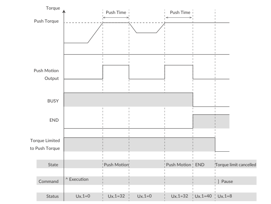
If the object cannot be detected during the Push Motion and the set target position is reached, Ux.1=296 (Operation Warning 256 + Push Motion 32 + In-position 8) is output; the query ?199 then replies the Push Motion Warning WARN.1=1.
If the Pause command is sent during Push Motion, the motion pauses but the Push Motion Holding Time is not cleared; the paused Push Motion resumes when the Restart command [ is sent.
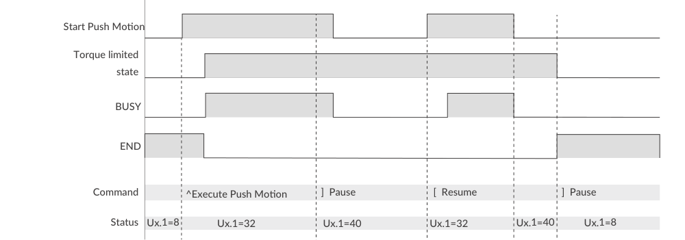
If the Pause command is sent twice during Push Motion, the Push Motion is terminated and the torque limit is cancelled.
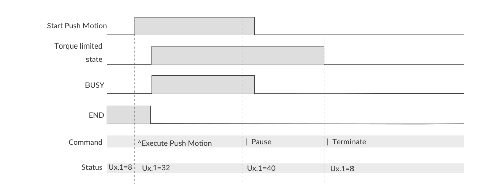
Push Motion signal output is valid only when the function is assigned to an output by Output Function selection.
Origin Detection by Command
Origin Detection is started with the execution command |. The signal source and method are selected with K22:
|
K22 |
Content |
|---|---|
|
0 / 1 |
Stopper Detection / Stopper Detection (Auto) |
|
2 / 3 |
Origin Sensor / Origin Sensor (Auto) * |
|
4 / 5 |
Stopper Detection + Z Phase Signal / same (Auto) |
|
6 / 7 |
Origin Sensor + Z Phase Signal / same (Auto) * |
|
8 / 9 |
Z Phase Signal / Z Phase Signal (Auto) |
* Valid only when the origin sensor is assigned to Input 1 (K44=1). "Auto" starts Origin Detection automatically when the power is turned on. Related parameters: Origin Detection Speed (K23), Acceleration (K24), Direction (K25), Origin Offset Distance (K26) and its unit (K27), Stopper Detection Torque (K28), Input 1 Function (K44), Origin Detection Completion (K30) and Origin Set Completion Output (K54 - K57).
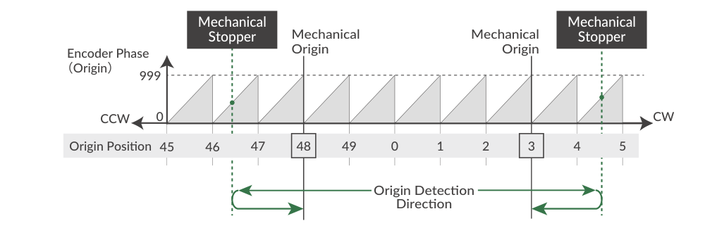
Stopper Detection: CM3 rotates in the set direction until the motor torque reaches the Stopper Detection Torque (K28, % of rated torque) and the speed drops to 1/16 of the Origin Detection Speed; the origin is then completed at the encoder phase 0 point one cycle before the detected phase. For a stable origin search, adjust the coupling so that the reported "Origin=***" phase value is between 200 and 800.
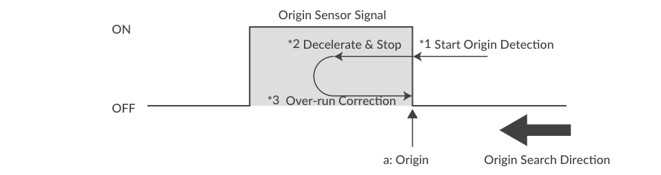
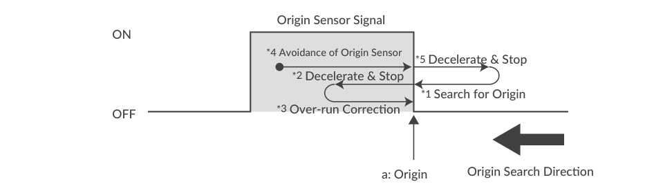
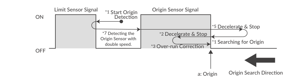
Origin Sensor: the origin sensor can be assigned only to IN1; the rising edge in the Origin Detection direction is detected as the mechanical origin.
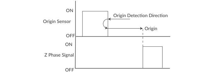
Z Phase Signal: output once per rotation from the internal encoder; Origin Detection using the Z phase always gives the same origin within one rotation, so a sensor can be omitted in applications such as rotary tables. Origin Offset is ignored when using the Z Phase Signal.
If Origin Detection is executed when the origin sensor is not assigned to Input 1, Ux.1=264 (256+8) is output and ?199 returns WARN.1=32 (operation warning). Related commands: |1 moves to position 0, |2 resets the current position to 0.
Full Origin Detection details: CM3 – Various Functions.
Manual Mode, Inching, Jog and Teaching
Turning on Input 4 puts CM3 into Manual Mode. In this mode Inputs 5 and 6 allow Inching and Jog motion (IN5 = CCW, IN6 = CW). Execution commands are not available in Manual Mode (sending one raises the Manual Mode Warning); the Teaching command # is available. In Manual Mode the Software Limit function is disabled.
|
K |
Name |
Setting / Range |
Unit |
Remarks |
|---|---|---|---|---|
|
50 |
Inching・Jog Speed |
1 - 32767 |
pps, set by K2 |
Speed for Inching and Jog operation. |
|
51 |
Inching Distance |
1 - 100 |
Pulse |
Inching travel per input signal. |
|
52 |
Inching・Jog Shift Time |
0: No Inching Motion / 1 - 3000 |
msec |
Time to switch to Jog after Inching completion. K52=0 enables Jog only. |
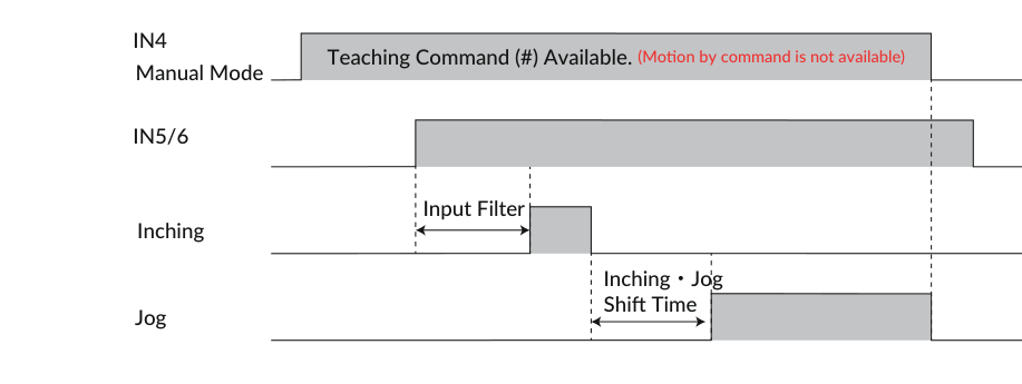
Inching/Jog example:
K2=0       // Set speed unit as 100 pps
K50=50     // Set Inching / Jog Speed as 50 x [100 pps] = 5000 pps
K51=100    // Set Inching Distance as 100 pulses
K52=1000   // Set Inching Shift Time as 1000 msec
When IN5 (IN6) is turned on, CM3 moves 100 pulses in the CCW (CW) direction as Inching. If the input remains on for 1000 msec or more after the Inching completes, the motion switches to Jog and continues rotating at 5000 pps while the input is on.
Teaching: with Manual Mode on, move CM3 to the desired position by Inching/Jog, then capture the current position into a Motion Data position with the # command:
#19 // Capture current position into Motion Data 19 (P19)
Servo On/Off by input: IN3 toggles Servo on (with alarm reset) and Servo off. When the signal turns on, the alarm is reset and the servo turns on at the same time (status Ux.1=8); when it turns off, the servo turns off (Ux.1=16).
Limit sensors: when a limit sensor turns on, CM3 sends the Operation Warning (Ux.1=256) and stops at the deceleration set in the Motion Data; ?199 returns the Limit Sensor Warning (WARN.1=4). After stopping, CM3 can only move in the opposite direction of the limit sensor. Example: K44=2 (CCW limit on IN1), K45=3 (CW limit on IN2).
Input Functions (Direct Type)
CM3 has 6 inputs. The functions of Input 1 and Input 2 are selectable with K44 and K45; the functions of Inputs 3 to 6 are fixed.
|
Input |
Function |
Description |
|---|---|---|
|
1 |
Limit・Origin Sensor |
Select Origin Sensor (K44=1) or CCW (K44=2) / CW (K44=3) limit sensor direction with K44. |
|
2 |
Limit Sensor |
Select CCW (K45=2) / CW (K45=3) limit sensor direction with K45. |
|
3 |
Servo on / Alarm Reset |
Toggle Servo on / Servo off. The alarm can be reset when the servo is turned on. |
|
4 |
Manual Mode |
Switch to Manual Mode. |
|
5 |
CCW Inching・Jog |
Inching/Jog in the CCW direction in Manual Mode. |
|
6 |
CW Inching・Jog |
Inching/Jog in the CW direction in Manual Mode. |
The input filter time is set with K42 (1 to 50 msec); signals shorter than the set value are not recognized. Input logic (Active High/Low per input) is set with K43. Details: CM3 – Input/Output.
Streaming Data (K85 – K90)
The Streaming Data function periodically outputs data such as the current position, speed and torque. Up to 4 channels (CH0 to CH3) can be sent at the same time in the format 01,[CH0],[CH1],[CH2],[CH3].
-
K85 - K88 (CH0 - CH3 Data): 0: Disabled, 1: Target Position, 2: Current Position, 3: Target Speed, 4: Current Speed, 5: Target Torque, 6: Current Torque, 7: Load Factor, 8: Voltage (0.1V), 9: Temperature (℃), 10: Input Status, 11: Output Status.
-
K89 (Streaming Interval): 1 - 30000 msec. Setting 5 msec or less can cause the interval to become unstable.
-
K90 (Streaming Setting): 0: Disabled, 1: Streaming all the time, 2: Streaming while operation. K90 always returns to Disabled when the power is turned on again (it cannot be saved).
[Sent Data]
K85=1      // Set Target Position for CH0
K86=2      // Set Current Position for CH1
K87=4      // Set Current Speed for CH2
K88=6      // Set Current Torque for CH3
K89=100    // Set Streaming Interval as 100 msec
K90=2      // Set Streaming Setting as "2: Streaming while operation"
^          // Execution Command

[Received Data]
  0 msec: 01,0,0,0,0
100 msec: 01,495,494,10200,4
200 msec: 01,1495,1495,10080,2
300 msec: 01,2494,2495,9960,3
400 msec: 01,3495,3496,10200,3
500 msec: 01,4494,4495,10200,1
Recovery from the STO State
When the voltage between STO+ and STO- is cut off, the STO function activates and CM3 goes into the STO status (Ux.1=1024). When voltage is applied again, the alarm becomes resettable and recovery is performed by commands:
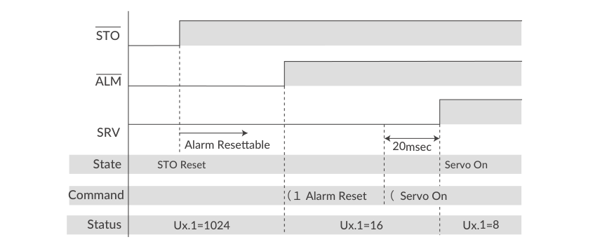
STO function details: CM3 – Various Functions.
Checking Status during Motion
Query commands can be sent at any time, including during motion, to build a sequence on the host side: ?96 (current position, Px.1=), ?97 (current speed, Sx.1=), ?98 (current torque, Ix.1=), ?99 (motor status, Ux.1=) and ?199 (warning detail, WARN.1=). Alternatively, the Status Report parameter (K66) makes CM3 report automatically to the host on in-position/alarm (B0), input status change (B1), output status change (B2), warning (B5) and more; for example K66=13 combines in-position/alarm report (1) + output status report (4) + no local echo (8). Details: CM3 – Detail of Various Settings.
Worked Examples
Example 1: Set Up and Run a PTP Positioning
V1=0       //Set PTP Motion to Motion Mode of Motion Data 1
P1=10000   //Set 10000 pulse to Position
S1=100     //Set 100 (Unit: K2) to Speed
A1=100     //Set 100 kpps² to Acceleration
$          //Save data (motor must be stopped)
^1         //Execute Motion Data 1
?99        //Query motor status during motion
Ux.1=0     //Reply: Moving
?96        //Query current position
Px.1=8452  //Reply: current position in pulses
?99        //Query motor status after motion
Ux.1=8     //Reply: In-position
Example 2: Push Motion with Pause and Terminate
K11=1      // One-direction, Set Time
K13=3000   // Push Motion Holding Time 3000 msec
V2=2       // PTP Push Motion
P2=10000   // Target position 10000 pulses
S2=20      // Speed 20 (Unit: K2)
A2=50      // Acceleration 50 kpps²
Q2=30      // Push Torque 30% of rated torque
^2         // Execute: Ux.1=32 during push, Ux.1=40 when completed
]          // Pause: push is paused, holding time not cleared
[          // Resume push motion
]          // Pause again
]          // Second ] terminates Push Motion, torque limit cancelled (Ux.1=8)
Example 3: Enable the Single Turn ABS Function (Power-Up by Commands)
K29=1      // Enable Single Turn ABS Function
$          // Send Data Save command
           // Turn off / on the power
           // ABS Alarm is ON (Ux.1=4096)
(1         // Reset Alarm    (Ux.1=16)
(          // Servo ON       (Ux.1=8)
|          // Complete the Origin Detection
The origin is cleared when the origin signal source or origin detection direction is changed; follow the above procedure again to set the origin.
Related Pages
-
CM3 – Wiring and Connection (sink/source connection examples, valistor, all cable pin-outs)
-
CM3 – Input/Output (input filter, input/output logic)
-
CM3 – Communication Functions (CWQ setup, control type selection)
-
CM3 – CML (COOL MUSCLE Language) (full parameter, Motion Data, execution and query tables for all types)
-
CM3 – Detail of Various Settings (K1 - K73 function details)
-
CM3 – Various Functions (origin detection, tuning, STO, streaming, status LED)
-
CM3 – Specifications (motor ratings, torque-speed curves, dimensions)