

9.1 Logic Bank
The Logic Bank does not define motion itself, but it can handle execution commands within the Logic Bank — Direct Mode and Motion Banks can be executed from the Logic Bank. The Logic Bank is executed cyclically. In combination with branching commands and comparison operators, CM3+ can constantly monitor input signals from sensors and its own motor information, and perform interrupt processing such as stopping motion in real time or overwriting the speed or target position. In other words, the CM3+ functions like a simple PLC.
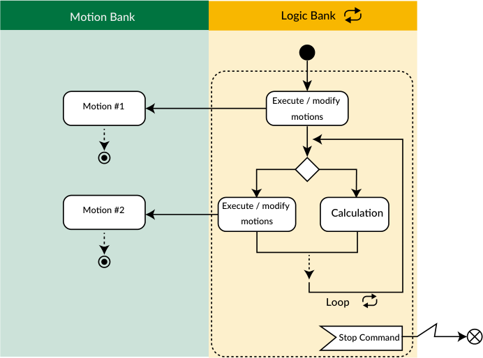
The Logic Bank loops over and over until it receives a stop command, executing/modifying motions, branching and performing arithmetic based on input signals.
What you can do with a Logic Bank
L1.1
V1.1=V2.1                  ... Assigning values
V1.1=V1.1+V3.1             ... Arithmetic operation
V1.1                       ... Displaying value
V1.1>V3.1,S.1=V4.1,T0.1    ... Branching process without any motion
I3.1,]1.1,T0.1             ... Branch processing by input signal
END
9.2 Execution of Logic Bank
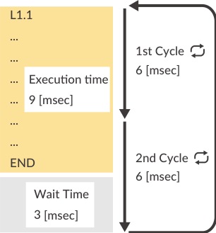
Unlike the Motion Bank, once the Logic Bank is executed it loops repeatedly in the cycle set by K82 until the stop command is sent.
[L1.1    // Execute Logic Bank 1
]L       // Stop Logic Bank
-
K81: Logic Bank No. executed when powered on — Logic Banks can start automatically at power-on without an execute command.
-
K82: Logic Bank execution cycle time.
Example:
P1.1=1000    // Define 1000 pulses for P1.1
L1.1         // Beginning of Logic Bank 1
P1.1         // Display data of P1.1
END          // END command
[L1.1        // Execute L1.1

Received: P1.1=1000 repeated at the cycle set by K82
In a Logic Bank, the processing time per command is 1 msec. If the execution time of the entire Logic Bank is longer than the execution cycle, the Logic Bank will be executed at integer multiples of the execution cycle.
9.3 Variable Command (V)
Variable commands (V commands) are often used in Logic Banks. Unlike commands directly related to operation (position, speed, acceleration, torque), V commands can handle the motor's internal data such as current position and numerical data for calculation. Using values set in V commands and motor-internal data, you can perform numerical operations, branch processing with comparison operators, and set values to other commands.
V Command Definition
Numerical values, character strings up to 4 single-byte alphanumeric characters, and motor internal variables can be specified. When specifying a character string or internal variable, enclose it in double quotation marks.
V3.1=1234       // Set 1234 to variable data 3 of ID1 (range -2147483648 to 2147483647)
V4.1="ABCD"     // Set the character string ABCD to variable data 4 of ID1
V5.1="Px"       // Set the current position to variable data 5 of ID1
Settable motor internal variables: Px (current position), Sx (current speed), Ix (current torque), Ux (current motor status), Pe (position error), PT (target position), ST (target speed).
1) Conditional branching by general data (operators can combine two data):
V2.1,?99.1,?98.1        // Execute ?99.1 when V2.1>0, otherwise ?98.1
V2.1==V3.1,?99.1,?98.1  // Execute ?99.1 when V2.1 equals V3.1, otherwise ?98.1

2) Numerical calculations:
P2.1=P1.1+V2.1          // Define the addition result of P1.1 and V2.1 in P2.1

3) Display defined contents (e.g. arbitrary message to host):
V4.1                    // Display the contents defined in V4.1
9.4 Branching by Input Status
By making the input point status a branch condition, events can be triggered by external signals.
L1.1
I2.1,?96.1,T0.1    // Display Px.1 (current position) only while IN2 is ON
END
T0.1 means "no action" — when IN2 is OFF, the program executes nothing and moves to the next line.
9.5 Execute and Stop Motion Bank
Motion Banks can be started and stopped from a Logic Bank. Combining branching by input points with Motion Bank execution allows motions to be executed and stopped from input points.
L1.1
I1.1,[1.1,T0.1    // Execute Motion Bank 1 when IN1 is ON
I2.1,].1,T0.1     // Stop Motion Bank 1 when IN2 is ON
END
9.6 Assigning the Internal Data
By setting the internal data to a V command and assigning it to another V command, the internal data can be treated as a numerical value.
V1.1="Px"    // Set current position in V1.1
V2.1=0       // Use V2.1 for calculation
L1.1
V2.1=V1.1    // Assign the value of V1.1 (current position) to V2.1
V2.1         // Display the value of V2.1 (current position)
END
To handle internal data as a numerical value, be sure to assign it to another V command. If you do not assign it, it will not be recognized as a numerical value.
9.7 Branching by Internal Data
By executing a Logic Bank simultaneously with a Motion Bank and using internal data as a branch condition, you can override the motion from within the Logic Bank without changing the Motion Bank.
Example: Continuous rotation; automatically change the speed to 10 when position exceeds 1000 pulses.
P1.1=1000000000   // Define continuous rotation in P1.1
A1.1=100
S1.1=100
B1.1
A1.1,S1.1,P1.1
END
V1.1="Px"         // Set current position to V1.1
V2.1=0            // Use V2.1 for calculation
V3.1=1000         // Define 1000 for comparison in V3.1
V4.1=10           // Set speed 10 to V4.1
L1.1
V2.1=V1.1         // Assign current position to V2.1
V2.1>V3.1,S0.1=V4.1,T0.1   // If position > 1000 pulses, change speed to 10
END
[1.1              // Execute Motion Bank
[L1.1             // Execute Logic Bank
You can override the target position, velocity, acceleration, and torque by changing P0, S0, A0, and M0 during motion.
9.8 Jump & Call
A Logic Bank can call and jump from the running Logic Bank to other Logic Banks, like the Motion Bank. Using jump and call commands, the whole sequence can be separated into routines and modularized.
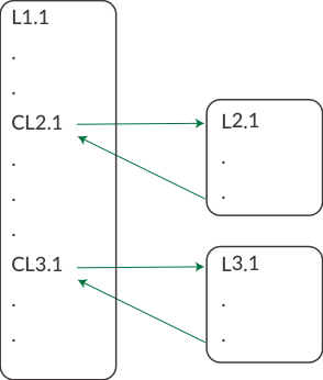
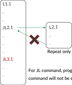
Both the CL and JL commands call other programs. The CL command returns to the caller after executing the called bank's sequence. The JL command does not return after jumping — the program after the jump command is not executed.
It is not possible to call or jump to a bank of another motor ID using the CL or JL command.
9.9 Various Conditional Branching
The Logic Bank supports various branching operations. Conditions of CM3+ and other devices in the application can be used for branching. Format: Condition, True to execute, False to execute
Single input (I command) and single variable (V command):
I1.1,JL2.1,JL3.1     // Jump to L2.1 when input 1 is on; jump to L3.1 when off
V3.1,CL2.1,CL3.1     // V3.1>0 calls L2.1; V3.1<=0 calls L3.1

Logical operators (only for I command):
I1.1&&I2.1,JL2.1,JL3.1   // Jump to L2.1 when inputs 1 and 2 are both on, otherwise L3.1

Comparison operators (only for V command):
V1.1>V2.1,[1.1,[2.1      // If V1.1 > V2.1 run B1.1, otherwise run B2.1
9.10 Operator
In the Logic Bank, operators are used to set numerical values and perform conditional branching: logical, comparison, and mathematical operators.
9.10.1 Logical Operators
Format: [Operand 1] Logical Operator [Operand 2]
|
Operator |
Function |
Example |
Description |
|---|---|---|---|
|
&& |
AND |
I1.1 && I3.1 |
When both input 1 and input 3 are true, execute the true condition; otherwise execute false |
|
|| |
OR |
I1.1 || I3.1 |
When either input 1 or input 3 is true, execute the true condition; otherwise execute false |
|
!! |
NOT |
I4.1 && !!(I3.1) |
When input 3 is true → false; when input 3 is false → true |
AND: When input 1 and input 2 are on, output 1 turns on.
L1.1
I1.1&&I2.1,O1.1,F1.1
END

OR: When either input 1 or input 2 is on, output 1 turns on.
L1.1
I1.1||I2.1,O1.1,F1.1
END

NOT: When input 1 is ON and input 2 is OFF, output 1 turns on.
L1.1
I1.1 && !!(I2.1),O1.1,F1.1
END
9.10.2 Comparison Operators
|
Operator |
Function |
Example |
Description |
|---|---|---|---|
|
== |
Equal |
V1.1 == V2.1 |
Execute TRUE when V1 equals V2 |
|
!= |
Not equal |
V1.1 != V2.1 |
Execute TRUE when V1 is not equal to V2 |
|
> |
Greater than |
V1.1 > V2.1 |
Execute TRUE when V1 is greater than V2 |
|
>= |
Greater than or equal |
V1.1 >= V2.1 |
Execute TRUE when V1 is greater than or equal to V2 |
|
< |
Less than |
V1.1 < V2.1 |
Execute TRUE when V1 is less than V2 |
|
<= |
Less than or equal |
V1.1 <= V2.1 |
Execute TRUE when V1 is less than or equal to V2 |
Example: Output 1 is ON only when V1.1 (motor status) is 8.
V1.1="Ux"
V2.1=0
V3.1=8
L1.1
V2.1=V1.1
V1.1 == V3.1,O1.1,F1.1
END
9.10.3 Arithmetic Operators
|
Operator |
Function |
Example |
|---|---|---|
|
= |
Set value |
P1.1= V1.1 |
|
+ |
Addition |
P1.1= P2.1+V1.1 |
|
- |
Subtraction |
P1.1= P2.1-V1.1 |
|
* |
Multiplication |
P1.1= P2.1*V1.1 |
|
/ |
Division |
P1.1= P2.1/V1.1 |
|
U1 |
Sine |
P1.1= U1(V1.1) — U1(θ)=10000×sin(2π×θ/36000), θ unit: 0.01 degree |
|
U2 |
Cosine |
P1.1= U2(V1.1) — U2(θ)=10000×cos(2π×θ/36000), θ unit: 0.01 degree |
|
U3 |
Square root |
P1.1= U3(V1.1) |