

4.1 Typical Connection Example
Caution about cabling
-
Be sure that the power is off before plugging or unplugging connectors.
-
Pay attention to straight insertion and removal of connectors by holding the connector's body.
-
Be sure there is no stress on connectors.
-
Do not pull cables hard or hang CM3+ by holding cables. It may result in damaged connectors.
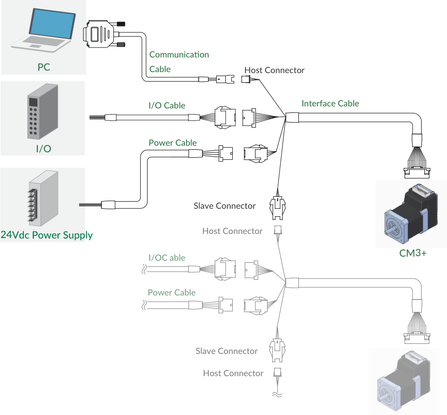
A typical system connects a PC (via interface cable to the host connector), a +24Vdc power supply (power cable), I/O (I/O cable), and additional CM3+ axes daisy-chained from slave connector to host connector with communication cables.
4.2 Connector Pin Layout and Functions
Main Connector
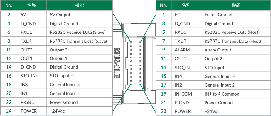
CM3+ has a 24-pin connector on the top (connector: 55959-2430, Molex). The pin layout, names and functions are as follows.
|
No. |
Name |
Function |
No. |
Name |
Function |
|---|---|---|---|---|---|
|
1 |
FG |
Frame Ground |
2 |
5V |
5V Output |
|
3 |
D_GND |
Digital Ground |
4 |
D_GND |
Digital Ground |
|
5 |
RXD0 |
RS232C Receive Data (Host) |
6 |
RXD1 |
RS232C Receive Data (Slave) |
|
7 |
TXD0 |
RS232C Transmit Data (Host) |
8 |
TXD1 |
RS232C Transmit Data (Slave) |
|
9 |
ALARM |
Alarm Output |
10 |
OUT3 |
Output 3 |
|
11 |
OUT2 |
Output 2 |
12 |
OUT1 |
Output 1 |
|
13 |
STO_IN- |
STO Input - |
14 |
D_GND |
Digital Ground |
|
15 |
IN4 |
General Input 4 |
16 |
STO_IN+ |
STO Input + |
|
17 |
IN2 |
General Input 2 |
18 |
IN3 |
General Input 3 |
|
19 |
IN_COM |
IN1 to 4 Common |
20 |
IN1 |
General Input 1 |
|
21 |
P-GND |
Power Ground |
22 |
P-GND |
Power Ground |
|
23 |
POWER |
+24Vdc |
24 |
POWER |
+24Vdc |
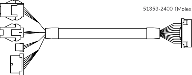
Interface Cable B (400mm, 1000mm, 2000mm, 3000mm, 5000mm)
Product Number: CMIFB1-****WR (****: cable length). Wires: pins 1–20 AWG26 UL20276 (80°C / 30V); pins 21–24 AWG24 UL20276 (80°C / 30V).
Communication Cable A (1000mm, 2000mm, 3000mm, 5000mm)
Product Number: CMRSA1-****W (****: cable length). Wires: AWG26 UL1007 (80°C / 300V).
|
Side |
Color |
No. |
Name |
Function |
|---|---|---|---|---|
|
PC side |
GRY |
2 |
TXD |
RS232C Transmit Data from PC |
|
PC side |
ORG |
3 |
RXD |
RS232C Receive Data from PC |
|
PC side |
WHT |
5 |
D_GND |
Digital Ground |
|
CM3+ side |
ORG |
1 |
RXD |
RS232C Receive Data from CM3+ |
|
CM3+ side |
GRY |
2 |
TXD |
RS232C Transmit Data from CM3+ |
|
CM3+ side |
WHT |
3 |
D_GND |
Digital Ground |
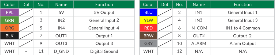
I/O Cable B (1000mm, 3000mm, 5000mm)
Product Number: CMIOB1-****S (****: cable length). Wires: AWG28 UL758 Style2464 (80°C / 300V).
|
Color |
No. |
Name |
Function |
|---|---|---|---|
|
PPL |
1 |
5V |
5V Output |
|
BLU |
2 |
IN1 |
General Input 1 |
|
GRN |
3 |
IN2 |
General Input 2 |
|
YLW |
4 |
IN3 |
General Input 3 |
|
ORG |
5 |
IN4 |
General Input 4 |
|
RED |
6 |
IN_COM |
IN1 to 4 Common |
|
BLK |
7 |
OUT1 |
Output 1 |
|
BRW |
8 |
OUT2 |
Output 2 |
|
WHT |
9 |
OUT3 |
Output 3 |
|
GRY |
10 |
ALARM |
Alarm Output |
|
WHT |
11 |
D_GND |
Digital Ground |
|
WHT |
12 |
N/A |
N/A |
Daisy Chain Cable A (500mm, 1000mm, 3000mm, 5000mm)
Product Number: CMDCA1-****S (****: cable length). Wires: AWG28 UL758 Style2464 (80°C / 300V).
Power Cable A (1000mm, 3000mm, 5000mm)
Product Number: CMPWA1-****S (****: cable length). Wires: AWG24 UL758 Style2464 (80°C / 300V).
|
Color |
No. |
Name |
Function |
|---|---|---|---|
|
RED |
1 |
POWER |
+24Vdc |
|
GRN |
2 |
POWER |
+24Vdc |
|
BLK |
3 |
P-GND |
Power Ground |
|
WHT |
4 |
P-GND |
Power Ground |
|
GRY |
5 |
STO_IN+ |
STO Input + |
|
BLU |
6 |
STO_IN- |
STO Input - |
|
BRW |
7 |
FG |
Frame Ground |
|
- |
8 |
N/A |
N/A |
4.3 Electrical Specifications
|
Item |
Parameter |
Value |
|---|---|---|
|
Digital Input |
Applied Voltage |
0 - 26 [V] |
|
Low Level Voltage |
0.8 [V] |
|
|
High Level Voltage |
4.2 [V] |
|
|
Digital Output |
Withstanding Voltage |
26 [V] |
|
Max. Continuous Load Current |
10 [mA] |
4.4 Input/Output Circuit
Inputs IN1–4 and STO have no polarity. Outputs OUT1–3 and ALARM are open-collector.
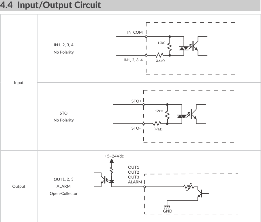
When not using the STO function, apply a voltage of 5 to 24V between STO+ and STO-.
4.5 Circuit Connection
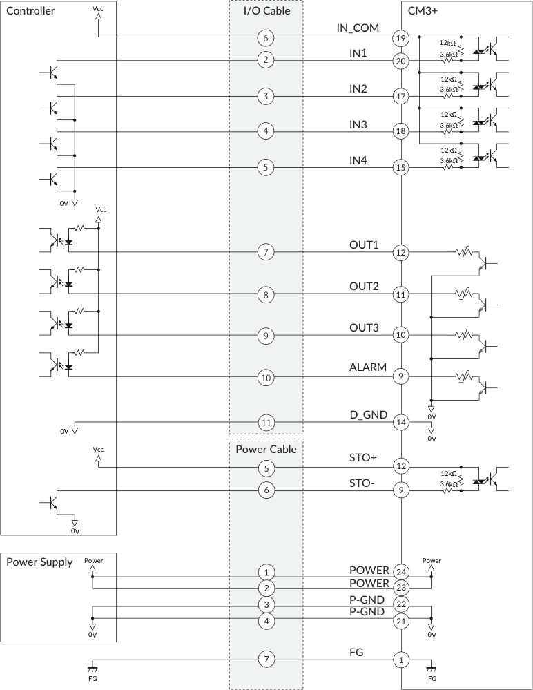
Connection Example with Sink Output Circuit
Connection Example with Source Output Circuit
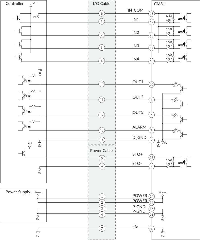
Make sure that the power is OFF while connecting the cables. Power ON only after confirming the wiring is thoroughly correct. Make sure to ground the FG.