

11.1 Origin Detection
Origin Detection can be selected from Stopper Detection, Origin Sensor, and combinations:
|
K22 |
Content |
|---|---|
|
0 |
Stopper Detection |
|
1 |
Stopper Detection (Auto) |
|
2 |
Origin Sensor * |
|
3 |
Origin Sensor (Auto) * |
* Valid only when the origin sensor is assigned to Input 1. "Auto" means origin detection starts automatically when the power is turned on. Related parameters: motion — K23 (speed), K24 (acceleration), K25 (direction); offset — K26 (distance), K27 (unit); stopper detection — K28 (torque); origin sensor — K44 (Input 1 function); completion — K30, and Origin Set Completion Output (K55/K56/K57).
11.1.1 Stopper Detection
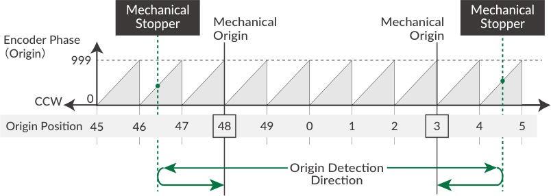
If the device has a mechanical stopper, origin search is available using the stopper as the origin signal source. There are 50 origin positions (mechanical origins) per rotation; the encoder phase shifts from 0 to 999 linearly between each origin position. When Origin Detection starts, CM3+ rotates in the set direction to detect the stopper. Stopper detection completes when the motor torque reaches the Stopper Detection Torque and the speed becomes 1/16 of the Origin Detection Speed; the encoder phase information (Origin=0 to 999) is then displayed. After stopper detection, Origin Detection completes at the encoder phase 0 point one cycle before the detected phase.
-
Set the stopper detection torque threshold as a percentage of max torque (K28). If set too low, the origin may be mis-detected.
-
When Origin Offset is set, the coordinate origin is the position moved by the offset distance from the detected mechanical origin.
-
For stable origin search, adjust the attachment (e.g. coupling) so the encoder phase value in "Origin=***" is between 200 and 800.
11.1.2 Origin Sensor
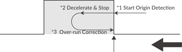
The origin sensor signal can only be assigned to IN1. The sensor detection circuit uses hysteresis to minimize noise influence. The rising edge of the origin sensor in the Origin Detection Direction is detected as the mechanical origin.
If origin detection is executed when the origin sensor is not assigned to Input 1, Ux.1=264 (256 Operation Warning + 8 In-position) is output and ?199 returns WARN.1=32. When selecting the Input 1 function (K44), be sure to select the origin sensor (K44=1) or the limit sensor in the origin detection direction (K44=2: CCW limit, K44=3: CW limit).
When the origin sensor signal is OFF at execution: (1) start origin detection; (2) decelerate from the rising edge of the origin sensor (point a); (3) move to point a again (over-run correction) — origin detection complete.
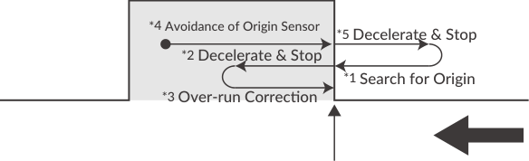
When the origin sensor signal is ON at execution: (1) run opposite to the origin detection direction to get out of the origin sensor; (2) after passing point a and detecting sensor off, decelerate; (3) then execute the same motion as the OFF case: start origin detection, decelerate from the rising edge (point a), move to point a again — complete.
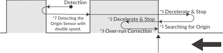
Simultaneous use of limit sensor and origin sensor: (1) start origin detection; (2) when the limit sensor in the origin detection direction is detected, move in the opposite direction at twice the origin detection speed; (3) detect the origin sensor signal; (4) execute the same motion as the "sensor ON" case; complete origin detection at point a.
11.2 Push Motion
Push Motion limits the output torque to the set torque for the set time. It can be used for gripping and press-fitting workpieces. To execute, use the Q command instead of the P command for the target position and set the Push Motion Operation Mode (K11), Push Motion Torque (K12) and Push Motion Holding Time (K13).
PTP / INC Push Motion
-
PTP Push Motion: starts Push Motion from the current position toward the set absolute position (Q command instead of P).
-
INC Push Motion: starts Push Motion with the target position at a distance from the current position (Q+ command instead of P+).
In either case, set the target position several revolutions ahead of the object to be pushed. If the target position is too small, positioning may complete before the workpiece is detected, or sufficient torque may not be generated. If the object cannot be detected and the set target position is reached, Ux.1=296 (256 Operation Warning + 32 Push Motion + 8 In-position) is output; ?199 replies WARN.1=1 (Push Motion Warning).
Push Motion Operation Mode (K11)
|
K11 |
Push Torque Direction |
Push Motion Time |
|---|---|---|
|
0 |
One direction |
Continuous |
|
1 |
One direction |
Set Time |
|
2 |
Both directions |
Continuous |
|
3 |
Both directions |
Set Time |
One direction: push torque is effective only in the operation direction (e.g. gripping a rigid workpiece). Both directions: effective in both directions (e.g. gripping an elastic workpiece or detecting a workpiece). Continuous: Push Motion does not stop until the stop command is sent, regardless of K13. Set Time: Push Motion completes when the total push time reaches K13.
Parameter example:
K11=1     // One direction, Set Time
K12=40    // 40% of rated torque
K13=3000  // Holding time 3000 msec
P2=10000  // Target Position 2 = 10000 pulses
S2=20     // Speed 2 (unit: K2)
A2=50     // Acceleration 2 = 50 kpps²

Program example:
B1.1               // Motion Bank 1 starts
A2.1,S2.1,Q2.1     // Push Motion using Q2 instead of P2
END
[1.1               // Execute Motion Bank
CM3+ enters Push Motion when its torque reaches 40% of rated torque (status Ux.1=32). Push Motion completes (Ux.1=40) when the total push time reaches 3000 msec.
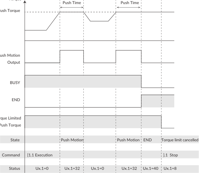
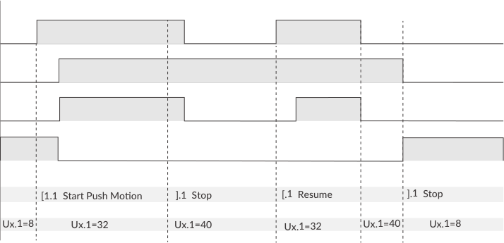
To resume Push Motion: if a pause command is sent during Push Motion, the motion pauses but the holding time is not cleared; the paused Push Motion resumes when the restart command is sent.
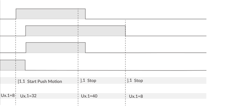
To execute the next motion: if the pause command is sent twice during Push Motion, Push Motion terminates and the torque limit is canceled.
Signal output is valid only when the function is assigned to an output by Output Function Selection.
11.3 Input Functions
CM3+ has 4 inputs; the functions of inputs 1 to 4 are set with K44 to K47.
|
K44/K45/K46/K47 |
Function |
Description |
|---|---|---|
|
0 |
General Input |
Set when using the I command |
|
1 |
Origin Sensor |
Available for IN1 only |
|
2 |
Limit Sensor (CCW) |
Limit sensor in CCW direction |
|
3 |
Limit Sensor (CW) |
Limit sensor in CW direction |
|
4 |
Manual Mode |
Switch to Manual Mode |
|
5 |
Servo ON/OFF |
Toggle Servo on/off. Alarm can be reset when the servo is turned on |
|
6 |
CCW Inching/Jog |
Only available for IN3 and IN4. Inching/Jog in the CCW direction in Manual Mode |
|
7 |
CW Inching/Jog |
Only available for IN3 and IN4. Inching/Jog in the CW direction in Manual Mode |
11.3.1 Input Filter
Set the filter time for the input signal with K42 between 1 and 50 msec. The higher the number, the longer the filter time and the slower the response. Signals shorter than the set value are not recognized. Example: K42=5.
11.3.2 Manual Mode
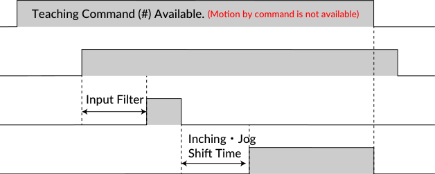
By turning on the Manual Mode input, CM3+ enters Manual Mode, in which the Inching/Jog inputs allow inching and jog motion. Execution commands are not available in Manual Mode (the teaching command # is available).
Example:
K2=0      // Speed unit 100 pps
K46=6     // Assign Inching/Jog (CCW) to Input 3
K47=7     // Assign Inching/Jog (CW) to Input 4
K50=50    // Inching/Jog speed = 50 x 100 pps = 5000 pps
K51=100   // Inching distance = 100 pulses
K52=1000  // Inching shift time = 1000 msec
When the input turns on, CM3+ moves the Inching Distance (K51) at the speed set by K50. If the input stays on longer than the Inching/Jog Shift Time (K52), the motion switches to Jog and continues rotating. If the input signal is shorter than K52, only the inching motion is executed.
Jog only: if K52=0, only Jog operation is enabled — CM3+ keeps rotating at the K50 speed while the input is ON.
11.3.3 Servo On / Servo Off
The Servo ON/OFF input toggles Servo on (with alarm reset) and Servo off. When the signal turns on, the alarm is reset and the servo turns on (status Ux.1=8, In-position). When the signal turns off, the servo turns off (Ux.1=16).
11.3.4 Limit Sensor
The limit sensor function can be set for Input 1 and Input 2 (e.g. K44=2 CCW limit to Input 1, K45=3 CW limit to Input 2). When the limit sensor turns on, CM3+ sends Operation Warning (Ux.1=256) and the motor stops at the deceleration set in the Motion Data; ?199 returns WARN.1=4 (Limit Sensor Warning). After stopping, CM3+ can only move in the opposite direction of the limit sensor.
11.4 Output Functions
CM3+ has 3 general outputs (OUT1–OUT3) and a dedicated ALARM output. Functions can be assigned to OUT1–OUT3.
11.4.1 Alarm Output
The alarm output function is assigned to the dedicated ALARM output. CM3+ goes into Servo Off when an alarm occurs, to protect itself. Alarm information can be confirmed by the Status LED (11.8) or the reply to Query command ?99 (7.2.2).
11.4.2 Other Output Functions
Three of the following output functions can be assigned to Outputs 1, 2 and 3 (K55, K56, K57):
|
K55/K56/K57 |
Function |
Output Contents |
|---|---|---|
|
0 |
General Output |
Turn outputs on/off by command |
|
1 |
In-position Output |
Output in the In-position range |
|
2 |
Warning Output |
Output in the Operation and Status Warning state |
|
3 |
N/A |
N/A |
|
4 |
ZONE Output |
Output in the ZONE set by parameters |
|
5 |
MOVE Output |
Output when speed exceeds the MOVE Output Threshold |
|
6 |
BUSY Output |
Output during motion |
|
7 |
END Output |
Output when operation is completed |
|
8 |
Servo On |
Output when Servo On |
|
9 |
Push Motion Output |
Output when torque exceeds the set value during Push Motion |
|
10 |
Origin Set Completion Output |
Output when origin is set |
Positioning status output (In-position, BUSY, END): CM3+ goes into In-position status and outputs the signal when the current position enters the In-position range (±) set by K5. When END Output is assigned, the output turns on when the operation set in Motion Data is completed. When the operation is paused, In-position Output turns on but END Output does not.
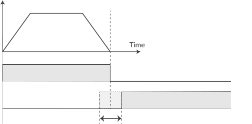
ZONE / MOVE Output: ZONE Output turns on when the current position is within the zone set by K59 (ZONE-) and K60 (ZONE+); valid for all operations. MOVE Output turns on when the speed exceeds the MOVE Output Threshold (K58). All output signals are valid only when the function is assigned to the output point.
11.5 Tuning
The servo tuning method can be selected from Tuningless or PPI control with the Tuning parameter (K31).
11.5.1 Tuningless (K31=1)
With Tuningless, CM3+ is automatically optimized for changes of load, motion, etc. from low to high speed range. When adjustment of trackability is necessary, use the Servo Stiffness parameter (K32) — the higher the value, the higher the trackability, but too high causes motor vibration.
11.5.2 PPI (K31=0)
For fixed load and operation, PPI control can be selected. Position P gain (K33), Speed P gain (K34), and Speed I gain (K35) are then valid and set separately to match your machinery. Without gain adjustment, vibration, over-sensitivity or noise may occur. Adjust with CM3+ mounted in the machine and running:
-
Initial setting: Position P gain=100, Speed P gain=150, Speed I gain=1.
-
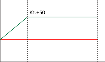
Speed P Gain (K34): increase K34 so that high-frequency vibration does not occur during operation. Setting it as high as possible (without vibration) is more stable. Even set value = Constant Gain Mode; odd = Variable Gain Mode (gain value applies at 0 rpm, increases in proportion between 0 and 300 rpm; conclusive gain = set value + 50).
-
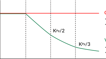
Position P Gain (K33): search for the optimum value while operating. Increasing it reduces position error and shortens positioning time, but too large causes vibration. Even = Constant Gain Mode; odd = Variable Gain Mode (set value applies at low speed; gain starts decreasing above 768 rpm, becoming one-third of the set value at 2304 rpm — e.g. K33=101 applies 100 below 768 rpm, 25 at 3000 rpm).
-
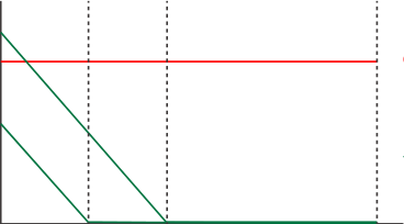
Speed I Gain (K35): increase after setting Position P Gain. It slowly corrects position error when it is not sufficiently reduced by Position P Gain; excessively high values cause large vibration. Even = Constant Gain Mode; odd = Variable Gain Mode (gain decreases with increasing speed; K35=5 becomes 0 above 30 rpm, K35=9 becomes 0 above 54 rpm).
11.5.3 S-Curve Gain
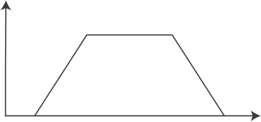
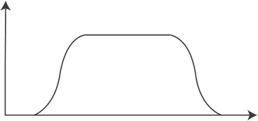
The S-curve gain (K36) changes the trapezoidal motion to an S-shape. K36 can be set from 0 to 1024 — the higher the value, the more S-shaped the motion. Enabling S-curve gain softens the impact when starting and stopping and reduces overshoot.
11.6 STO Function
CM3+ is equipped with the STO (Safe Torque Off) function, one of the safety functions defined in international standard IEC 61800-5-2. STO cuts off only the power supply to the motor. When STO is activated, the stopped state of the motor is not controlled and the servo is turned off.
If a voltage is applied between STO+ and STO-, STO stays disabled and CM3+ is ready to operate. When the voltage is cut off, STO activates and the status becomes Ux.1=1024. When voltage is applied again between STO+ and STO-, STO is canceled and the alarm can be canceled.
11.7 Streaming Data
The Streaming Data function periodically outputs data such as current position, speed, and torque. Up to 4 data types (CH0 to CH3) can be sent at the same time. Output format: 01,[CH0],[CH1],[CH2],[CH3]
Streaming Data Selection (K85 to K88)
|
Value |
Output Data |
Unit |
|---|---|---|
|
0 |
Disabled |
- |
|
1 |
Target Position |
Pulse |
|
2 |
Current Position |
Pulse |
|
3 |
Target Speed |
K2 |
|
4 |
Current Speed |
K2 |
|
5 |
Target Torque |
% of Max. Torque |
|
6 |
Current Torque |
% of Max. Torque |
|
7 |
Load Factor |
% of Rated Torque |
|
8 |
Voltage |
0.1V |
|
9 |
Temperature |
℃ |
|
10 |
Input Status |
- |
|
11 |
Output Status |
- |
Streaming Interval (K89): sets the data output interval. Setting it to 5 msec or less can cause the interval to become unstable.
Streaming Setting (K90): 0: Disabled (no data streaming); 1: Streaming all the time (to stop, set K90=0); 2: Streaming while operating (data only while the motor is running). K90 always returns to the default "Disabled" when the power is turned on again.
Example:
K85=1    // Target Position for CH0
K86=2    // Current Position for CH1
K87=4    // Current Speed for CH2
K88=6    // Current Torque for CH3
K89=100  // Streaming interval 100 msec
K90=2    // Streaming while operating
^        // Execution command

Received:
    0 msec:  01,0,0,0,0
  100 msec:  01,495,494,10200,4
  200 msec:  01,1495,1495,10080,2
  300 msec:  01,2494,2495,9960,3
  400 msec:  01,3495,3496,10200,3
  500 msec:  01,4494,4495,10200,1
11.8 Status LED
The status of CM3+ is indicated by the 7-color status LED (blue, green, red, magenta, cyan, yellow, white). Each status has its own flashing pattern; if multiple statuses occur at the same time, the status nearer the top of the table has higher priority.
|
Status |
Pattern |
Red |
Magenta |
Green |
Cyan |
Blue |
White |
Yellow |
|---|---|---|---|---|---|---|---|---|
|
STO |
Lighting |
Red |
|
|
|
|
|
|
|
Overload Alarm |
Alternate |
Red |
Magenta |
|
|
|
|
|
|
Over Current Alarm |
Alternate |
Red |
|
Green |
|
|
|
|
|
Over Temperature Alarm |
Alternate |
Red |
|
|
Cyan |
|
|
|
|
Over Voltage Alarm |
Alternate |
Red |
|
|
|
Blue |
|
|
|
Low Voltage Alarm |
Alternate |
Red |
|
|
|
|
White |
|
|
Position Error Overflow Alarm |
Flashing |
Red |
|
|
|
|
|
|
|
ABS Alarm |
Alternate |
Red |
|
|
|
|
|
Yellow |
|
Servo Off |
Lighting |
|
Magenta |
|
|
|
|
|
|
Push Motion Warning |
Flashing |
|
|
|
|
|
|
Yellow |
|
Limit Sensor |
Alternate |
|
|
Green |
|
|
|
Yellow |
|
Software Limit |
Alternate |
|
|
|
|
Blue |
|
Yellow |
|
Manual Mode Warning |
Lighting |
|
|
|
|
|
|
Yellow |
|
Operation Warning |
Alternate |
|
|
|
|
|
White |
Yellow |
|
Overload Warning |
Alternate |
|
Magenta |
|
|
|
|
Yellow |
|
Temperature Warning |
Alternate |
|
|
|
Cyan |
|
|
Yellow |
|
Servo On |
Lighting |
|
|
|
|
Blue |
|
|
|
BUSY* |
Lighting |
|
|
Green |
|
|
|
|
|
Push Motion |
Flashing |
|
|
Green |
|
|
|
|
|
In The Manual Mode |
Alternate |
|
|
|
|
Blue |
White |
|
LED lighting for BUSY means motion is being executed. It may not match the BUSY output during operation (Ux.1=0) — confirm the exact status by communication.