

1.1 Overview
The COOL MUSCLE 3 series is designed to provide servo motor equivalent performance with the same ease of use as a stepping motor while maintaining the size of the COOL MUSCLE 1, and is available in two models, COOL MUSCLE 3 and COOL MUSCLE 3+.
COOL MUSCLE 3+ (hereinafter referred to as CM3+) adds new functions to the basic performance of the CM3 and is very easy to use for engineers. It has multi-axis control and PLC functions, making it a more customizable and highly functional motor. With its full range of functions, this model is suitable for those who want to make a full-scale effort from the creation of software.
Integrated but Compact Design
Since the motor, encoder, driver, controller, and network functions are integrated, a system can be built without a control panel and without the need for a separate driver or controller. In addition, it is more compact than the conventional CM1 but has more powerful performance.
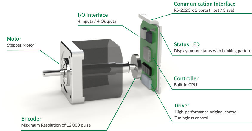
|
Component |
Description |
|---|---|
|
Motor |
Stepper Motor |
|
Encoder |
Maximum resolution of 12,000 pulses |
|
I/O Interface |
4 Inputs / 4 Outputs |
|
Communication Interface |
RS-232C x 2 ports (Host / Slave) |
|
Status LED |
Displays motor status with blinking pattern |
|
Controller |
Built-in CPU |
|
Driver |
High-performance original control, tuningless control |
Multi-axis network with reduced wiring
The network configuration uses a daisy chain method. A multi-axis network with up to 15 axes can be constructed simply by connecting the motors with cables. There is no need to connect to a separate driver or controller, making it possible to start up the device speedily without the trouble of wiring.
Simplest operation
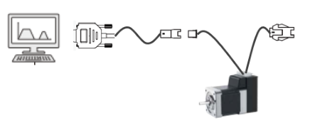
The interface with the host controller uses serial communication (RS-232C). If you are in an environment where you can communicate, you do not need any special equipment or software to operate.
Simple program setting / saving
It is possible to set a program that controls the motor and save it in the built-in CPU with only a combination of multiple letters and numbers.
P=1000   ...Set position as 1000
S=100    ...Set speed as 100
A=10     ...Set acceleration as 10
This program is called CML (COOL MUSCLE Language) and is displayed in ASCII code. You can intuitively execute various operations just by sending and receiving CML. See Chapter 6 CML (COOL MUSCLE Language).
Protective functions
The following protection functions are installed for safe operation: soft limit / hard limit function, speed override function, over current protection function, position deviation overflow function, over voltage detection function, low voltage detection function, internal temperature monitor function, overload function, STO (Safe Torque Off) function, and reverse connection prevention function.
Multi-tasking processing
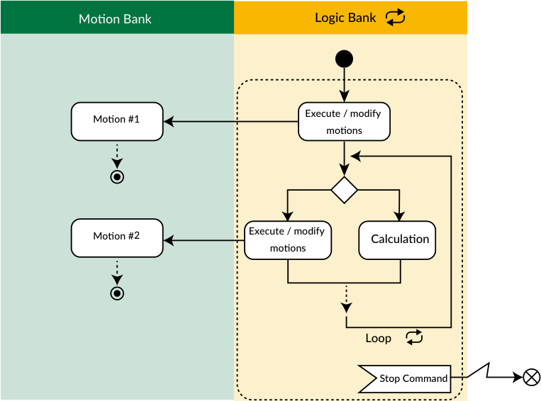
There are two types of CM3+ programs: Motion Banks, which describe motion sequences such as positioning, and Logic Banks, which describe the entire sequence. These programs can be executed simultaneously.
|
Motion Bank |
Logic Bank |
|---|---|
|
Program about motion sequence |
Program about the whole sequence |
|
Run only once (does not repeat automatically) |
Executed cyclically |
|
|
Motion can be executed and changed |
While the Motion Bank is executed only once in response to an execution command, the Logic Bank is executed repeatedly in the background until a stop command is issued. This means that data such as input signal ON/OFF, current position of the motor, speed, and torque are periodically monitored, and when conditions are met, changes can be made to the motion in real time through branch processing.
Example of operation using a Logic Bank
|
Motion Bank only |
Motion Bank + Logic Bank |
|---|---|
|
When the home position is far away, the home detection operation is slow and takes a long time. |
Starts home detection at high speed and slows down when the sensor before the home sensor turns ON. |
|
Stops when a signal is received during continuous rotation. The sensor must be aligned with the position to be stopped. |
Stops after moving an arbitrary distance from the point where the signal is received. |
|
Always positions in the same direction with the table mechanism. |
Compares clockwise and counterclockwise rotation and rotates in the closer direction. |
1.2 Flowchart for Operation
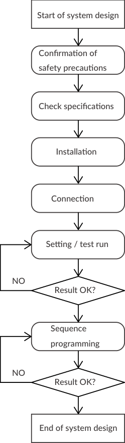
The flowchart below shows the flow until CM3+ is operated. Please follow the steps carefully.
-
Be sure to read the safety precautions before use. See Instructions for Safety.
-
After confirming the model and characteristics of the CM3+ to be used, confirm that the environment in which it is used is within the characteristic range. See Chapter 13 Specifications.
-
Check the precautions for installation. See Chapter 3 Installation.
-
Make wiring and connection. Be sure to check the wiring after completing it. See Chapter 4 Wiring and Connection.
-
Even with multiple axes, be sure to set and check the operation for each single axis. See Chapter 7 Test Run and Settings.
-
Program the sequence. See Chapter 8 Program Function.