

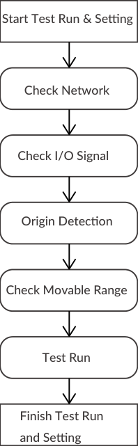
In this chapter, the flow to the test run is explained. The purpose is to set the appropriate parameters for each axis and make the motion sequence safe and executable by performing a trial run: [1] check network, [2] check I/O signal, [3] origin detection, [4] check movable range, [5] test run (check the torque while operating and adjust the gain). Check connections, wiring, and operating area before starting.
7.1 Forming Daisy Chain Network
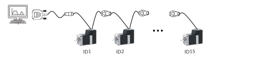
The CM3+ network uses the Daisy Chain network method in which devices are connected in a row. When forming a network, it is necessary to detect each CM3+ in the network by numbers, called motor IDs. The motor IDs are automatically assigned when power is supplied — lower ID closer to the host device. Therefore, when forming a network with multiple axes, the power must be supplied to all CM3+ at the same time.
The default communication specifications for CM3+ are shown below:
|
Item |
Value |
|---|---|
|
Baud rate |
38400 bps |
|
Data length |
8 bit |
|
Parity |
None |
|
Stop bit |
1 |
|
Flow control |
None |
Set the communication on the host device as shown above and confirm network establishment using terminal software such as TeraTerm. When, for example, a 3-axis network is established, the ID numbers and version information will be sent to the host device.
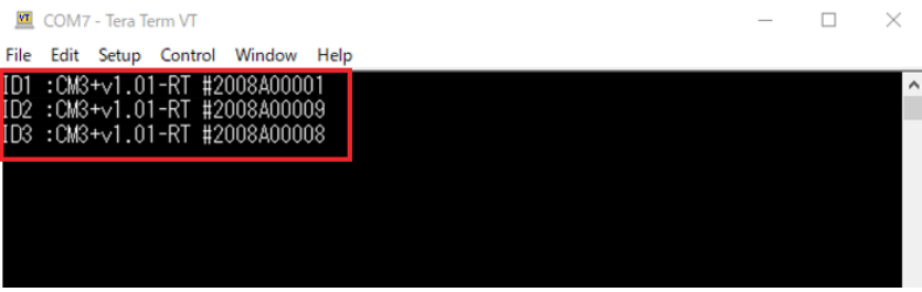
If the network is not established, multi-axis control by CML is not possible. Be sure to check the establishment of the network. If all IDs are not displayed even though communication settings match, check: (1) Is the wiring correct? (2) Is the line feed (LF) deleted on the host device?
7.2 CML Used for Test Run
Once the network is established, you can start to check various things using CML execution commands, query commands and parameters. Commands are sent in the following format:
"CML Command" No.ID    (No is omitted if not required)
Example: O3.2    // Turn on output signal 3 of motor ID2
7.2.1 Execution Commands
|
CML |
Name |
No |
Detail |
|---|---|---|---|
|
^ |
Execution of Direct Motion Data |
|
Start motion with data registered for direct execution |
|
] |
Stop |
|
Stop |
|
| |
Start Origin Detection |
|
Origin detection operation start (according to K22 to K30 set values) |
|
|1 |
Move to coordinate 0 |
|
Move to coordinate 0 |
|
|2 |
Reset current position |
|
Set the current position to coordinate 0 |
|
O |
Turn on general output |
1 - 3 |
Turn on the output specified by No |
|
F |
Turn off general output |
1 - 3 |
Turn off the output specified by No |
|
) |
Servo off |
|
Turn off the servo |
|
(1 |
Alarm reset |
|
Reset the alarm |
|
( |
Servo on |
|
Turn on servo |
|
$ |
Save Data |
|
Saves all the data |
7.2.2 Query Commands
|
CML |
Name |
Unit |
Reply Contents |
|---|---|---|---|
|
? |
Direct Mode Motion Data |
N/A |
Displays the definition contents of S0, A0, P0. Example: ?.1 → S.1=500, A.1=2000, P.1=100000 |
|
?50 |
Output Status |
N/A |
Displays output status in hexadecimal, OUT.1 = hex value (0: Off / 1: On). B0: Output 1, B1: Output 2, B2: Output 3, B3: ALARM output |
|
?70 |
Input Status |
N/A |
Displays input status in hexadecimal, IN.1 = hex value (0: Off / 1: On). B0-B3: Input 1-4, B6: STO Signal, B7: Over Current Signal |
|
?71 |
Temperature in Driver Case |
℃ |
Temp.1=Value |
|
?72 |
Power Voltage |
0.1V |
CVSEN.1=Value |
|
?79 |
Load Factor |
% |
PWR.1=Value — percentage of rated torque |
|
?85 |
Version Information |
N/A |
Display version information |
|
?90 |
List of Parameters |
N/A |
Display the list of all K parameters |
|
?95 |
Position Deviation |
Pulse |
Pe.1=Value |
|
?96 |
Current Position |
Pulse |
Px.1=Value |
|
?97 |
Current Speed |
Set by K2 |
Sx.1=Value |
|
?98 |
Current Torque |
% |
Ix.1=Value — percentage of the max torque |
|
?99 |
Motor Status |
N/A |
Displays motor status in decimal, Ux.1=decimal value. See Motor Status Bit Values below. Warning contents can be checked by ?199. |
|
?999 |
All Data List |
N/A |
|
|
?1000 |
All Motion Bank |
N/A |
|
Motor Status Bit Values
The reply to ?99 is a decimal number, Ux.ID=Value. Each status bit has a fixed decimal value. Usually only one bit is on, so the reply matches one row directly. Example: Ux.1=512 means motor ID1 has a Low Voltage Alarm.
|
Bit |
Decimal value |
Meaning |
Type |
|---|---|---|---|
|
B0 |
1 |
Position Error Overflow |
Alarm |
|
B1 |
2 |
Overvoltage Alarm |
Alarm |
|
B2 |
4 |
Overload Alarm |
Alarm |
|
B3 |
8 |
In-position |
Status |
|
B4 |
16 |
Servo off |
Status |
|
B5 |
32 |
Push Motion |
Status |
|
B6 |
64 |
Over Current Alarm |
Alarm |
|
B7 |
128 |
Temperature Alarm |
Alarm |
|
B8 |
256 |
Operation Warning (details with ?199) |
Warning |
|
B9 |
512 |
Low Voltage Alarm |
Alarm |
|
B10 |
1024 |
STO Activated |
Status |
|
B11 |
2048 |
Status Warning (details with ?199) |
Warning |
|
B12 |
4096 |
ABS Alarm |
Alarm |
If more than one bit is on, the reply is the sum of their values. Example: Ux.1=528 = 512 + 16 = Low Voltage Alarm and Servo off. Subtract the largest value that fits, then repeat until the remainder is 0.
7.2.3 Warning Query Command
Warning information can be checked with the Warning Query Command (?199, reply WARN.1=Value). Since a warning is a state before the alarm, the motor will not be Servo off. Utilizing warnings helps preventive maintenance of CM3+.
|
Bit |
Warning |
Category |
Cause |
|---|---|---|---|
|
B0 |
Push Motion Warning |
Operation |
Reached the target position during Push Motion |
|
B1 |
Software Limit Warning |
Operation |
Execution command sent to a target position over the software limit |
|
B2 |
Limit Sensor Warning |
Operation |
Limit sensor is on |
|
B3 |
Manual Mode |
Operation |
Execution command sent in Manual Mode |
|
B4 |
N/A |
N/A |
N/A |
|
B5 |
Execution Warning |
Operation |
An operation command is sent when operation cannot be performed |
|
B6 |
Temperature Warning |
Status |
Temperature inside driver case exceeds the set value of K61 |
|
B7 |
Over Load Warning |
Status |
The load exceeds the set value of K62 |
Numbers for Parameter Setting
If B0 to B# is written in the Setting/Range column of the parameter list, the setting is made in bit units. The contents set to 1 are valid, and the contents set to 0 are invalid. When setting parameters, convert the binary number to a decimal number before setting. Example: binary 01001100b ⇒ decimal 76 ⇒ K##.1 = 76[CRLF]
7.3 Parameter Setting
Set parameters such as resolution, communication settings, and protection functions. Details of the various functions and usage examples are described in Chapter 10.
Setting format:       K Parameter Number = Value [CRLF]
Confirmation format:  K Parameter Number [CRLF]

Example — set 10000 pulses to the positive Software Limit and enable it:
K10=100[CRLF]    // The pulse unit of the Software Limit is 100 pulses
K7=1[CRLF]

Confirming example:
K7[CRLF]         // Send to CM3+
K7.1=1[CRLF]     // Sent from CM3+ to host
Change parameters while CM3+ is stopped. Unless the Data Save command ($) is executed, the previously saved value will remain when the power is turned on again. For safety reasons, some settings require a power off and on (Restart — marked ✓ in the tables below).
7.3.1 Motion Environmental Parameters
|
K |
Name |
Setting/Range |
Unit |
Restart |
Reference/Remarks |
|---|---|---|---|---|---|
|
1 |
Resolution |
0: 300 / 1: 600 / 2: 1000 / 3: 1200 / 4: 2000 / 5: 3000 / 6: 5000 / 7: 6000 / 8: 10000 / 9: 12000 |
ppr |
✓ |
Set the pulse count per revolution. Ref: 10.1 |
|
2 |
Speed Unit |
0: 100 / 1: 10 / 2: 1 |
pps |
✓ |
Set the speed unit for S command |
|
3 |
Servo ON/OFF Setting |
0: Servo Off / 1: Servo On |
|
|
Set whether CM3+ starts with Servo on or off when powered on |
|
4 |
Coordinate Direction |
0: Positive in CW / 1: Positive in CCW |
- |
✓ |
Set the coordinate direction. Ref: 10.2 |
|
5 |
In-position Range |
1 - 500 |
Pulse |
|
Set the range for In-position. Ref: 10.3 |
|
6 |
Speed Override |
1 - 100 |
% |
|
Limit the speed by the set proportion. Ref: 10.4 |
|
7 |
Software Limit Setting |
0: Disabled / 1: Detect before moving / 2: Detect after moving |
- |
|
Enable/disable the software limit function and its operation. Ref: 10.5 |
|
8 |
Software Limit (+) |
0 - depends on Resolution |
Pulse (unit set by K10) |
|
Set the operating limit boundary in the positive direction. Ref: 10.5 |
|
9 |
Software Limit (-) |
Depends on Resolution - 0 |
Pulse (unit set by K10) |
|
Set the operating limit boundary in the negative direction. Ref: 10.5 |
|
10 |
Unit of Software Limit |
0: 100 / 1: 10 / 2: 1 |
Pulse |
✓ |
Set the unit for Software Limit. Ref: 10.5 |
|
11 |
Push Motion Operation Mode |
0: Continuous (One direction) / 1: Set time (One direction) / 2: Continuous (Both directions) / 3: Set time (Both directions) |
- |
|
Set the direction and time for Push Motion. One direction: torque limited only in operation direction; both directions: torque limited in both directions |
|
12 |
Push Motion Torque |
10 - 100 |
% |
|
Set the torque during pressing operation by command Q or Z in % of the rated torque |
|
13 |
Push Motion Holding Time |
1 - 30000 |
msec |
|
Set Push Motion holding time. Ref: 8.6.2 |
|
14 |
Open Loop Holding Angle |
0: Disabled / 1 - 72 |
±0.1° |
|
Set the angle difference between target and current position to switch back to closed loop from Open Loop Holding. Ref: 10.6 |
|
15 |
Switch Time for Open Loop Holding Mode |
10 - 1000 |
msec |
|
Set the time to switch to Open Loop Holding after positioning is completed. Ref: 10.6 |
|
16 |
Deceleration Ratio |
1 - 500 |
% |
|
Set the deceleration in % of the A command |
|
17 |
Creeping Speed |
0 - 1000 |
K2 |
|
Set the creeping speed. Ref: 10.7 |
7.3.2 Origin Detection Parameters
|
K |
Name |
Setting/Range |
Unit |
Restart |
Reference/Remarks |
|---|---|---|---|---|---|
|
22 |
Origin Signal Source |
0: Stopper Detection / 1: Stopper Detection (Auto) / 2: Origin Sensor / 3: Origin Sensor (Auto) |
- |
✓ |
Set the origin detection signal source and detection method. The origin sensor can only be assigned to input point 1. (Auto): automatic origin detection starts at power on. Ref: 11.1 |
|
23 |
Origin Detection Speed |
1 - 32767 |
pps (set by K2) |
|
Set the speed for Origin Detection |
|
24 |
Origin Detection Acceleration |
1 - 32767 |
kpps² |
|
Set the acceleration for Origin Detection |
|
25 |
Origin Detection Direction |
0: CW / 1: CCW |
- |
✓ |
Set the direction for Origin Detection |
|
26 |
Origin Offset Distance |
±32767 |
pulse |
|
Set offset amount from detected origin to coordinate origin |
|
27 |
Unit of Origin Offset Distance |
0: 100 / 1: 10 / 2: 1 |
pulse |
✓ |
Set the unit when Offset is set |
|
28 |
Stopper Detection Torque |
10 - 150 |
% |
|
Set the torque to detect a stopper for Origin Detection by percentage of rated torque. Ref: 11.1.1 |
|
29 |
Single Turn ABS Function |
0: Disabled / 1: Enabled |
- |
✓ |
Enable/disable the Single Turn ABS function. Ref: 10.8 |
|
30 |
Origin Detection Completion |
0: Disabled / 1: Enabled |
- |
✓ |
Function will not operate until origin detection is completed. Ref: 10.9 |
7.3.3 Gain Adjustment Parameters
|
K |
Name |
Setting/Range |
Unit |
Restart |
Reference/Remarks |
|---|---|---|---|---|---|
|
31 |
Tuning |
0: PPI / 1: Tuningless |
- |
|
Set CM3+ tuning method. Ref: 11.5 |
|
32 |
Servo Stiffness |
10 - 200 |
|
|
Set servo stiffness when Tuningless is selected. Ref: 11.5.1 |
|
33 |
Position P Gain |
1 - 5000 |
|
|
Set 3 types of gains when PPI is selected. Ref: 11.5.2 |
|
34 |
Speed P Gain |
50 - 5000 |
|
|
Set 3 types of gains when PPI is selected. Ref: 11.5.2 |
|
35 |
Speed I Gain |
0 - 5000 |
|
|
Set 3 types of gains when PPI is selected. Ref: 11.5.2 |
|
36 |
S-Curve Gain |
0 - 1024 |
|
|
Set S-Curve gain for positioning operation. Ref: 11.5.3 |
7.3.4 I/O Parameters
|
K |
Name |
Setting/Range |
Unit |
Restart |
Reference/Remarks |
|---|---|---|---|---|---|
|
42 |
Input Filter |
1 - 50 |
msec |
✓ |
Set the filtering time for input signals. Ref: 11.3.1 |
|
43 |
Input Logic |
Digits 1-4 = IN1-IN4; 0: Active High, 1: Active Low |
|
✓ |
Set the input logic. Ref: 5.1.2. Ex: IN1 and IN3 as Active Low → K43=0101 |
|
44 / 45 / 46 / 47 |
Input 1 / 2 / 3 / 4 Function |
0: No Action / 1: Origin Sensor / 2: CCW Limit Sensor / 3: CW Limit Sensor / 4: Manual Mode / 5: Servo on-off / 6: Inching-Jog (CCW) / 7: Inching-Jog (CW) |
|
✓ |
Select the function assigned to IN1 to IN4. Origin sensor can only be assigned to IN1. Inching/jog can only be assigned to IN3 and IN4. Ref: 11.3 |
|
50 |
Inching / Jog Speed |
1 - 32767 |
pps (set by K2) |
|
Set the speed for Inching and Jog operation. Ref: 11.3.2 |
|
51 |
Inching Distance |
1 - 100 |
Pulse |
|
Set the Inching distance. Ref: 11.3.2 |
|
52 |
Inching / Jog Shift Time |
0: No Inching Motion / 1 - 3000 |
msec |
|
Set the time to switch from Inching completion to Jog. Ref: 11.3.2 |
|
53 |
Output Logic |
Digits 1-3 = OUT1-OUT3; 0: Active High, 1: Active Low |
|
✓ |
Set the output logic. Ref: 5.2.2. Ex: OUT3 and OUT1 as Active Low → K53=101 |
|
55 / 56 / 57 |
Output 1 / 2 / 3 Function |
0: General Output / 1: In-position Output / 2: Warning Output / 3: Individual ZONE Output / 4: ZONE Output / 5: MOVE Output / 6: BUSY Output / 7: END Output / 8: Servo On Output / 9: Push Motion Output / 10: Origin Set Completion Output |
|
|
Assign functions to Output 1 to 3. Ref: 11.4.2 |
|
58 |
MOVE Output Threshold |
0 - 2147483648 |
pps (set by K2) |
|
Set the speed threshold to output the MOVE Output signal. Ref: 11.4.2 |
|
59 |
ZONE (-) |
±2147483647 |
Pulse |
|
Set boundary of ZONE Output in the negative direction. Ref: 11.4.2 |
|
60 |
ZONE (+) |
±2147483647 |
Pulse |
|
Set boundary of ZONE Output in the positive direction. Ref: 11.4.2 |
7.3.5 Status Parameters
|
K |
Name |
Setting/Range |
Unit |
Restart |
Reference/Remarks |
|---|---|---|---|---|---|
|
61 |
Temperature Warning Threshold |
0 - 100 |
℃ |
|
Set the threshold to output a temperature warning |
|
62 |
Load Warning Threshold |
0 - 100 |
% |
|
Set a threshold to output a load warning as a percentage of the maximum torque |
|
63 |
Position Error Overflow Threshold |
1 - 32767 |
1000 pulse |
|
Set Position Error Overflow Threshold between current and target position. Ref: 10.10 |
|
64 |
Overload Detection Time |
100 - 10000 |
msec |
|
Set the time to output Overload alarm. Ref: 10.11 |
|
65 |
Status LED |
0: Enabled / 1: Disabled |
|
|
Enable/disable the status LED. Ref: 11.8 |
|
66 |
Status Report |
B0: In-position/Alarm (Ux.1) / B1: Input Status (IN.1) / B2: Output Status (OUT.1) / B3: No Local Echo / B4: Comment / B5: Warning (Ux.1) |
|
|
Set the conditions to automatically report to a host controller. Ref: 10.12 |
7.3.6 Communication Parameters
|
K |
Name |
Setting/Range |
Unit |
Restart |
Reference/Remarks |
|---|---|---|---|---|---|
|
71 |
Baud Rate for Host Communication |
0: 38.4 / 1: 9.6 / 2: 19.2 / 3: 57.6 / 4: 115.2 |
kbps |
|
Set the baud rate. Ref: 10.13 |
|
72 |
Parity |
0: None / 1: Even / 2: Odd |
|
|
Set the parity when transferring data |
|
73 |
Delimiter |
0: CR / 1: CRLF |
|
|
Set the delimiter type at the end of replied data from CM3+ |
|
74 |
Baud Rate for Slave Communication |
0: 38.4 / 1: 9.6 / 2: 19.2 / 3: 57.6 / 4: 115.2 |
kbps |
|
Set the communication baud rate between slaves when multiple CM3+ are daisy-chained. Ref: 10.13 |
7.3.7 Logic Bank Parameters
|
K |
Name |
Setting/Range |
Unit |
Restart |
Reference/Remarks |
|---|---|---|---|---|---|
|
81 |
Logic Bank No. to be executed at power on |
0 - 30 |
|
|
Sets the Logic Bank number executed when power is turned on. If 0, no Logic Bank is executed. Ref: 9.2 |
|
82 |
Logic Bank Execution Cycle |
1 - 30000 |
msec |
✓ |
Sets the execution cycle of the Logic Bank; it will be executed cyclically at the set period. Ref: 9.2 |
7.3.8 Monitoring Parameters
|
K |
Name |
Setting/Range |
Unit |
Restart |
Reference/Remarks |
|---|---|---|---|---|---|
|
85 / 86 / 87 / 88 |
CH0 / CH1 / CH2 / CH3 Data |
0: Disabled / 1: Target Position (pulse) / 2: Current Position (pulse) / 3: Target Speed (K2 value) / 4: Current Speed (K2 value) / 5: Target Torque (% of max) / 6: Current Torque (% of max) / 7: Load Factor (% of rated) / 8: Voltage (0.1V) / 9: Temperature (℃) / 10: Input Status / 11: Output Status |
- |
|
Output data can be set on up to 4 channels. Ref: 11.7 |
|
89 |
Streaming Interval |
1 - 30000 |
msec |
|
Set the time interval to output Streaming Data. Ref: 11.7 |
|
90 |
Streaming Setting |
0: Disabled / 1: Streaming all the time / 2: Streaming while operating |
|
|
Set the timing to stream data (cannot be saved). Ref: 11.7 |
7.4 Checking I/O Connection
The CM3+ has 4 inputs, 3 outputs and 1 STO input. Use CML to check the wiring, then check the electrical specifications with measuring devices. Refer to 4.5 Circuit Connection for connection examples.
-
Turn off the servo. If the servo is on, send the servo off command ").ID". Send the motor status query "?99.ID" and confirm that Ux.ID = 16.
-
Parameter setting. Assign "General Input" to IN1-IN4 (K44.ID=0, K45.ID=0, K46.ID=0, K47.ID=0) and "General Output" to OUT1-OUT3 (K55.ID=0, K56.ID=0, K57.ID=0).
-
Check the input signal. Turn off all input signals (Input 1-4 and STO) then send "?70.ID" — expect IN.1=0000. Turn on all inputs and STO then send "?70.ID" — expect IN.1=004F. If you can see the change in input status, the connection is correct. (Depending on the connection, the status logic may be reversed.)
-
Confirm electrical specifications of input signals. Measure the high and low level voltages with measuring devices and make sure the specifications in 13.2 Electrical Specifications are met — especially with long wiring. When using switches with mechanical contacts, check chattering and adjust the input filter (K42): measure the chattering period T and set K42 > T [msec].
-
Check the output signal. Use the CML execution commands "O" and "F" to check responses from the connected devices (e.g. O2.3 turns on output 2 of motor ID3; F1.3 turns off output 1 of motor ID3). Connect not exceeding the maximum rated current.
7.5 Origin Setting
Since the position coordinates of CM3+ are incremental, it is necessary to set the origin (coordinate 0) every time CM3+ is turned on. There are two types of origin signal sources: Stopper and Origin Sensor (refer to 11.1 Origin Detection). When the origin signal source is not used, it is also possible to set the current position as the origin using the execution command from the host device. If you do not use the execution command, the position when the power is turned on is 0.
|.1     // CM3+ with ID1 starts the origin detection operation
|2.2    // Set the current position of ID2 as the origin
7.6 Checking Range of Motion
Check the coordinates of the target position for interference with the machine, other axes, and wiring routing. CM3+ sets the target position in pulse units. There are two ways to check: using motion data for direct execution, or using the jog function of the input function. Since the area is checked on the hardware side, check with the set speed slowed down as much as possible. The confirmation method using the jog function:
-
Calculate the range of motion (related parameter K1: Resolution) from the machine specifications.
-
Parameter setting: K44.ID=5 (Servo On to Input 1), K45.ID=4 (Manual Mode to Input 2), K46.ID=6 (Inching/Jog CCW to Input 3), K47.ID=7 (Inching/Jog CW to Input 4), K50.ID=10 (jog speed), K52.ID=0 (no inching motion). See 11.3.2 Manual Mode for Inching/Jog operation.
-
Origin detection. When using an origin sensor as the origin signal source, set Origin Sensor to Input 1 by K44. Use the execution command to turn the servo on and off.
-
Check the operating range by jog operation: confirm the current position at the maximum point matches the calculation (?96.ID returns Px.ID=****); check for interference with other axes; check the routing of wiring (bending radius, no load on the main connector).
After confirming the maximum operating area, you can carry out the test run more safely by using the Software Limit function (K8 and K9).
7.7 Operation Confirmation
From here, operate CM3+ by sending execution commands from the host device. First set position, speed and acceleration for direct execution, then start (^) and stop (]) the operation.
Points for checking operation: tuning (Gain Adjustment Parameters K31 to K36) and torque during task (Monitoring Parameters K85 to K90). Refer to 11.5 Tuning. Make sure the torque during the task is within the allowable range — torque may differ by installation conditions (see Chapter 3 Installation).
Position
A unit of angle for positioning is defined as 1 pulse. The number of pulses per rotation of the output shaft is called Resolution, unit ppr (pulses per revolution). The default Resolution is 1000 and it can be set from 300 to 12000 ppr by parameter.
Speed
The number of pulses moved per second is defined as 1 pps. The unit of speed is 100 pps by default and can be selected from 100, 10 or 1 pps by parameter (K2).
Example: K2=0 (100pps), S=100  ->  S.1 = 100 x 100pps = 10000 [pps]

Unit conversion to rpm:
Speed[rpm] = S Data x Speed Unit [pps] x 60 [sec/min] / Resolution [ppr]
Example: S=100, K2=0 (100pps), K1=2 (1000ppr)
Speed[rpm] = 100 x 100 x 60 / 1000 = 600 [rpm]
Acceleration
The rate of increase in velocity per second is defined as acceleration, unit pps². The unit of acceleration data "A" is kpps² (kilo-pulse/sec²) = 1000 pps².
Example: K2=0 (100pps), S=500, A=100
Acceleration Time [sec] = 500 x 100 [pps] / (100 x 1000 pps²) = 0.5 [sec]
After calculating the trajectory of motion, set the motion data (position, velocity, acceleration) in CM3+:
P2.1=10000   // Set 10000 pulses to Position of Motion Data 2
S2.1=50      // Set 5000 pps to Speed of Motion Data 2 (unit set by K2)
A2.1=10      // Set 10 kpps² to Acceleration of Motion Data 2

^.2          // CM3+ with ID2 starts operation according to the motion data
].2          // Stop the operation of CM3+ with ID2
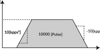
When CM3+ reaches the target position or is stopped by the stop command, the In-position status Ux.2=8 will be sent to the host device, the same as when positioning is completed.