

2.1 Product Code Scheme
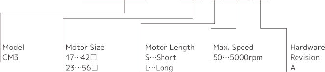
The CM3+ product code scheme is described as below (example: CM3+-17L50A).
|
Product Name |
Product Code |
|---|---|
|
CM3+ 42 Short |
CM3+-17S50A |
|
CM3+ 42 Long |
CM3+-17L50A |
|
CM3+ 56 Short |
CM3+-23S50A |
|
CM3+ 56 Long |
CM3+-23L50A |
2.2 Function Block Diagram
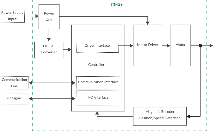
The CM3+ integrates the controller, driver interface, communication interface, I/O interface, power unit, DC-DC converter, motor driver, motor, and magnetic encoder (position/speed detection) in a single package.
2.3 Parts Description
The names of the parts of CM3+ are as shown below: motor, mounting holes (4 corners), flange, output shaft, rabbet, main connector, status LED, and driver case. The status LED displays the motor status with LED blinking patterns.
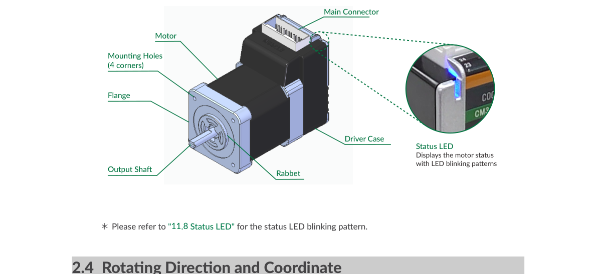
Please refer to "11.8 Status LED" for the status LED blinking patterns.
2.4 Rotating Direction and Coordinate
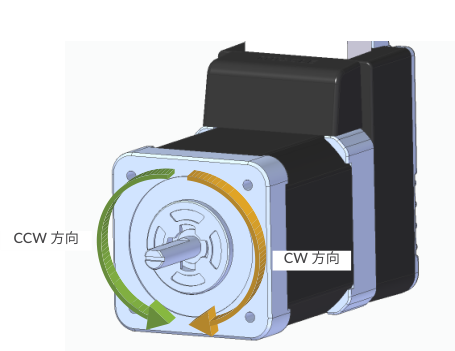
Rotating direction and coordinates are defined as below:
-
CW (Clockwise) Direction: clockwise direction as viewed from the output shaft side.
-
CCW (Counterclockwise) Direction: counterclockwise direction as viewed from the output shaft side.
Coordinate Direction
By the default setting, CW direction is the positive direction and CCW direction is the negative direction in the coordinate system. The coordinate direction can be reversed by parameter. Ref: 10.2 Coordinate Direction (K4).