

5.1 Input Signal
5.1.1 Input Filter
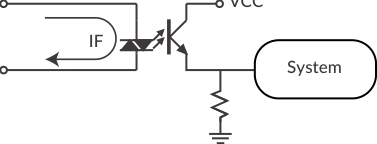
CM3+ has 4 digital inputs, IN1 to IN4, which do not come with polarity. A filter function (1 to 50 msec) by software is available on all inputs. The filter function by software cannot be removed. The minimum filtering time is 1 msec, and the detection sequence is shown in the diagram below.
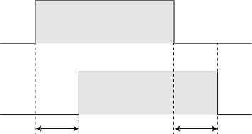
When the Input Filter is set, a signal shorter than the set time is not detected as a signal.
5.1.2 Input Logic
Input signal logic can be set by a parameter. Active High and Active Low settings are available — set to suit the logic on the controller side.
5.2 Output Signal
5.2.1 Output Function
The outputs (OUT1 to OUT3 and ALARM) are open collector outputs. ALARM is a dedicated alarm output; the functions of OUT1 to OUT3 can be selected by parameters.
5.2.2 Output Logic
When selecting "User Defined" in the Output Function parameter, the logic for Output 1 to Output 3 can be switched.
-
Active High: gate in open-collector circuit is ON when the output condition is true.
-
Active Low: gate in open-collector circuit is ON when the output condition is false.
The ALARM output is fixed as Active Low logic.
Refer to 11.4 Output Functions for further information.