
Communication Objects
0x1000: Device Type
Provides information on the device type.
|
Sub-index |
Description |
Range |
Default |
Type |
Access |
PDO Mapping |
|---|---|---|---|---|---|---|
|
0x00 |
Device Type |
0x00-0xFFFFFFFFh |
0x00040192 |
UDINT |
ro |
No |
Explanation of set value
|
Bits |
Name |
Description |
|---|---|---|
|
0-15 |
Device Profile Number |
402 (0x192): Drive Profile |
|
16-23 |
Type |
04: Step motor |
|
24-31 |
Mode |
0: Manufacturer specific |
0x1001: Error Register
Indicates the error type that occurs in the slave device. The generic error bit is set on all errors. Specific error codes can be found in object 0x603F: Error Code
|
Sub-index |
Description |
Range |
Default |
Type |
Access |
PDO Mapping |
|---|---|---|---|---|---|---|
|
0x00 |
Error Register |
0x00-0xFF |
0x00 |
USINT |
ro |
No |
Definition of bits:
|
Bit |
Error Description |
|---|---|
|
0 |
Generic |
|
1 |
Current |
|
2 |
Voltage |
|
3 |
Temperature |
|
4 |
Communication Error |
|
5 |
Device profile specific |
|
6 |
N/A |
|
7 |
Manufacturer specific |
0x1008: Manufacturer Device Name
Indicates the manufacturers device name
|
Sub-index |
Description |
Range |
Default |
Type |
Access |
PDO Mapping |
|---|---|---|---|---|---|---|
|
0x00 |
Manufacturers Device Name |
- |
"CM1-E" |
STRING |
ro |
No |
0x1009: Manufacturer Hardware Version
Indicates the EtherCAT hardware version.
|
Sub-index |
Description |
Range |
Default |
Type |
Access |
PDO Mapping |
|---|---|---|---|---|---|---|
|
0x00 |
Manufacturer Hardware Version |
- |
"MYO28-04F" |
STRING |
ro |
No |
0x100A: Manufacturer Software Version
Indicates the version of the EtherCAT firmware
The version is a 9-character string, padded at the end with spaces. Firmware 1.3.12 reports "1.3.12" followed by three spaces.
|
Sub-index |
Description |
Range |
Default |
Type |
Access |
PDO Mapping |
|---|---|---|---|---|---|---|
|
0x00 |
Manufacturer Software Version |
- |
"1.3.12" |
STRING |
ro |
No |
0x1018: Identity Object
Indicates general device information
|
Sub-index |
Description |
Range |
Default |
Type |
Access |
PDO Mapping |
|---|---|---|---|---|---|---|
|
0x00 |
Number of Entries |
0x01-0x04 |
0x04 |
USINT |
ro |
No |
|
0x01 |
Vendor ID |
0x00-0xFFFFFFFF |
0x00004441 |
UDINT |
ro |
No |
|
0x02 |
Product Code |
0x00-0xFFFFFFFF |
0x44412002 |
UDINT |
ro |
No |
|
0x03 |
Revision Number |
0x00-0xFFFFFFFF |
0x20020103 |
UDINT |
ro |
No |
|
0x04 |
Serial Number |
0x00-0xFFFFFFFF |
0x00000000 |
UDINT |
ro |
No |
PDO Mapping Objects
0x1600: Receive PDO mapping parameter - Dynamic switching of modes
|
Sub-index |
Description |
Value |
Access |
PDO Mapping |
|---|---|---|---|---|
|
0x00 |
Number of entries |
0x07 |
ro |
No |
|
0x01 |
Controlword mapping |
0x60400010
|
ro |
No |
|
0x02 |
Target position mapping |
0x607A0020
|
ro |
No |
|
0x03 |
Target velocity mapping |
0x60FF0020 |
ro |
No |
|
0x04 |
Digital outputs mapping |
0x60FE0010
|
ro |
No |
|
0x05 |
Mode of operation mapping |
0x60600008
|
ro |
No |
0x1601: Receive PDO mapping parameter - CSP mode
|
Sub-index |
Description |
Value |
Access |
PDO Mapping |
|---|---|---|---|---|
|
0x00 |
Number of entries |
0x04 |
ro |
No |
|
0x01 |
Controlword mapping |
0x60400010
|
ro |
No |
|
0x02 |
Target position mapping |
0x607A0020
|
ro |
No |
|
0x03 |
Digital outputs mapping |
0x60FE0010
|
ro |
No |
0x1602: Receive PDO mapping parameter - CSV mode
|
Sub-index |
Description |
Value |
Access |
PDO Mapping |
|---|---|---|---|---|
|
0x00 |
Number of entries |
0x04 |
ro |
No |
|
0x01 |
Controlword mapping |
0x60400010
|
ro |
No |
|
0x02 |
Target velocity mapping |
0x60FF0020 |
ro |
No |
|
0x03 |
Digital outputs mapping |
0x60FE0010
|
ro |
No |
0x1603: Receive PDO mapping parameter - Profile mode
|
Sub-index |
Description |
Value |
Access |
PDO Mapping |
|---|---|---|---|---|
|
0x00 |
Number of entries |
0x06 |
ro |
No |
|
0x01 |
Controlword mapping |
0x60400010
|
ro |
No |
|
0x03 |
Target Position mapping |
0x607A0020
|
ro |
No |
|
0x04 |
Target Velocity mapping |
0x60FF0020 |
ro |
No |
|
0x05 |
Profile Velocity mapping |
0x60810020 |
ro |
No |
|
0x06 |
Profile Acceleration mapping |
0x60830020 |
ro |
No |
|
0x07 |
Mode of operation mapping |
0x60600008 |
ro |
No |
0x1A00: Transmit PDO mapping parameter - Dynamic switching of modes
|
Sub-index |
Description |
Value |
Access |
PDO Mapping |
|---|---|---|---|---|
|
0x00 |
Number of entries |
0x0B |
ro |
No |
|
0x01 |
Statusword mapping |
0x60410010 |
ro |
No |
|
0x02 |
Position actual value mapping |
0x60640020 |
ro |
No |
|
0x03 |
Velocity actual value mapping |
0x606C0020
|
ro |
No |
|
0x04 |
Torque actual value mapping |
0x60770020
|
ro |
No |
|
0x05 |
Digital input mapping |
0x60FD0010
|
ro |
No |
|
0x06 |
Error code mapping |
0x603F0010 |
ro |
No |
|
0x07 |
Temperature-C mapping |
0x23010010
|
ro |
No |
|
0x08 |
DC voltage mapping |
0x60790010
|
ro |
No |
|
0x09 |
Modes of operation display mapping |
0x60610008
|
ro |
No |
0x1A01: Transmit PDO mapping parameter - CSP mode
|
Sub-index |
Description |
Value |
Access |
PDO Mapping |
|---|---|---|---|---|
|
0x00 |
Number of entries |
0x07 |
ro |
No |
|
0x01 |
Statusword mapping |
0x60410010 |
ro |
No |
|
0x02 |
Position actual value mapping |
0x60640020 |
ro |
No |
|
0x03 |
Velocity actual value mapping |
0x606C0020
|
ro |
No |
|
0x04 |
Torque actual value mapping |
0x60770020
|
ro |
No |
|
0x05 |
Digital input mapping |
0x60FD0010
|
ro |
No |
|
0x06 |
Error code mapping |
0x603F0010 |
ro |
No |
0x1A02: Transmit PDO mapping parameter - CSV mode
|
Sub-index |
Description |
Value |
Access |
PDO Mapping |
|---|---|---|---|---|
|
0x00 |
Number of entries |
0x07 |
ro |
No |
|
0x01 |
Statusword mapping |
0x60410010 |
ro |
No |
|
0x02 |
Position actual value mapping |
0x60640020 |
ro |
No |
|
0x03 |
Velocity actual value mapping |
0x606C0020
|
ro |
No |
|
0x04 |
Torque actual value mapping |
0x60770020
|
ro |
No |
|
0x05 |
Digital input mapping |
0x60FD0010
|
ro |
No |
|
0x06 |
Error code mapping |
0x603F0010 |
ro |
No |
0x1A03: Transmit PDO mapping parameter - Profile mode
|
Sub-index |
Description |
Value |
Access |
PDO Mapping |
|---|---|---|---|---|
|
0x00 |
Number of entries |
0x0B |
ro |
No |
|
0x01 |
Statusword mapping |
0x60410010 |
ro |
No |
|
0x02 |
Position actual value mapping |
0x60640020 |
ro |
No |
|
0x03 |
Velocity actual value mapping |
0x606C0020
|
ro |
No |
|
0x04 |
Torque actual value mapping |
0x60770020
|
ro |
No |
|
0x05 |
Digital input mapping |
0x60FD0010
|
ro |
No |
|
0x06 |
Error code mapping |
0x603F0010 |
ro |
No |
|
0x07 |
Temperature-C mapping |
0x23010010
|
ro |
No |
|
0x08 |
DC voltage mapping |
0x60790010
|
ro |
No |
|
0x09 |
Mode of operation display mapping |
0x60610008 |
ro |
No |
CiA402 Drive Profile Objects
0x6007: Abort Connection Option Code
Sets the reaction when the EtherCAT slave leaves OP. Available from firmware 1.3.12.
|
Sub-index |
Description |
Range |
Default |
Type |
Access |
PDO Mapping |
|---|---|---|---|---|---|---|
|
0x00 |
Abort Connection Option Code |
0-3 |
1 |
INT |
rw |
No |
The value is not stored: it returns to 1 at every power-up.
|
Value |
Reaction when the slave leaves OP |
|---|---|
|
0 |
No action. CSV/CSP set points freeze and the motor holds its last position, still energised. PV, PP and Homing keep running at their last command. |
|
1 (default) |
Fault. The motor is disabled and the axis goes to Fault, with 0x603F = 0x7500 and 0x1001 = 0x11. Clear it with a fault reset (controlword bit 7). |
|
2 |
Disable voltage. The motor is disabled and the axis goes to Switch On Disabled. No fault is raised. |
|
3 and any other value |
Handled as 1. Quick stop is not implemented. |
The reaction applies to every exit from OP: SM watchdog timeout or cable pull, a change to SAFEOP, PREOP or INIT requested by the master, and a TwinCAT runtime stop.
To use 0 or 2, add a CoE startup entry in TwinCAT so the value is written every time the drive starts: Startup tab, New, Transition P -> S, Index 6007, Sub-Index 0, value 0 or 2.
Communication loss is detected by the SM watchdog. In TwinCAT it is set on the EtherCAT tab under Advanced Settings > Behavior > Set SM Watchdog (default 1000 = 100 ms). With the SM watchdog disabled, a cable pull is not detected until the master changes the state.
0x6007 is not a safety function. For an emergency stop, remove the 24 V drive power through a safety relay.
0x603F: Error Code
Indicates specific error code when an error occurs.
|
Sub-index |
Description |
Range |
Default |
Type |
Access |
PDO Mapping |
|---|---|---|---|---|---|---|
|
0x00 |
Error Code |
0x0000-0xFFFF |
0x0000 |
UINT |
ro |
No |
The following table outlines the error and the relevant objects that are set.
|
0x603F Error Code |
0x1001 Error Register |
0x6041 Fault (Bit 3) |
Description |
|---|---|---|---|
|
0x0000 |
0x00 |
0 |
No error |
|
0x2310 |
0x03 |
1 |
Continuous over current error (torque overload) |
|
0x4310 |
0x09 |
1 |
Drive over temperature |
|
0x4502 |
0x00 |
0 |
No mode selected (0x6060=0)1 |
|
0x7310 |
0x81 |
1 |
Over speed error |
|
0x7320 |
0x81 |
1 |
Position Error overflow |
|
0x7500 |
0x11 |
1 |
EtherCAT communication lost: slave left OP, reaction set by 0x6007 |
|
0x7510 |
0x11 |
1 |
Internal motor serial link lost |
|
0x7520 |
0x11 |
1 |
Cannot switch the motor to cyclic (CIA) mode |
|
0x8611 |
0x00 |
0 |
Motor not currently following commanded position 1,2 |
|
0xFF01 |
0x00 |
0 |
Motor disabled by command1 |
|
0xFF02 |
0x81 |
1 |
Push-mode torque limit fault |
|
0xFF03 |
0x81 |
1 |
Push-mode timeout |
|
0xFF04 |
0x81 |
1 |
Emergency stop active |
|
0xFF05 |
0x11 |
0/13 |
24V drive power not present |
-
Not an error state
-
The motor is not following because for example the FSM state is not in Operation Enabled.
-
If the FSM is in Operation Enabled the loss of 24V power will generate a fault on the statusword
otherwise the fault bit will not show an error.
Clearing errors
-
A fault reset (controlword 0x0080) clears 0x603F and 0x1001 together with the fault bit. 0x603F then reads 0x8611 in Switch On Disabled and Ready to Switch On, and 0 from Switched On.
-
A fault that is still present is reported again.
-
The fault reset is refused while the motor serial link is down and drive power is off.
-
Masters that need the last error should log 0x603F when the fault bit rises.
0x6040: Controlword
|
Sub-index |
Description |
Type |
Access |
PDO Mapping |
|---|---|---|---|---|
|
0x00 |
Used to control the drive's state machine |
UINT |
rw |
Yes |
For more information on the Controlword usage see the chapter CiA 402 - Drives and Motion Control Device Profile
0x6041: Statusword
|
Sub-index |
Description |
Type |
Access |
PDO Mapping |
|---|---|---|---|---|
|
0x00 |
Displays the status of the drive's state machine |
UINT |
ro |
Yes |
For more information on the Statusword usage see the chapter CiA 402 - Drives and Motion Control Device Profile
0x6060: Modes of operation
|
Sub-index |
Description |
Type |
Access |
PDO Mapping |
|---|---|---|---|---|
|
0x00 |
Set the desired mode of operation |
SINT |
rw |
Yes |
|
Value |
Mode of Operation |
|---|---|
|
0 |
No mode selected |
|
3 |
Profile Velocity (PV) Mode |
|
6 |
Homing Mode (HM) |
|
8 |
Cyclic Synchronois Position (CSP) Mode |
|
9 |
Cyclic Synchronous Velocity (CSV) Mode |
0x6061: Modes of operation display
|
Sub-index |
Description |
Type |
Access |
PDO Mapping |
|---|---|---|---|---|
|
0x00 |
Read the mode of operation currently set on the drive |
SINT |
ro |
Yes |
|
Value |
Mode of Operation |
|---|---|
|
0 |
No mode selected |
|
3 |
Profile Velocity (PV) Mode |
|
8 |
Cyclic Synchronois Position (CSP) Mode |
|
9 |
Cyclic Synchronous Velocity (CSV) Mode |
0x6064: Position actual value
|
Sub-index |
Description |
Type |
Access |
PDO Mapping |
|---|---|---|---|---|
|
0x00 |
Read the actual position of the motor.
(50,000 pulses/revolution) |
DINT |
ro |
Yes |
0x606C: Speed actual value
|
Sub-index |
Description |
Type |
Access |
PDO Mapping |
|---|---|---|---|---|
|
0x00 |
Read the actual speed of the motor.
(50,000 pulses/revolution) |
DINT |
ro |
Yes |
0x6072: Peak torque
|
Sub-index |
Description |
Type |
Access |
PDO Mapping |
|---|---|---|---|---|
|
0x00 |
Read the peak torque of the motor.
|
UINT |
ro |
Yes |
0x6073: Motor max current
|
Sub-index |
Description |
Type |
Access |
PDO Mapping |
|---|---|---|---|---|
|
0x00 |
Read the max current of the motor.
|
UINT |
ro |
No |
0x6075: Motor rated current
|
Sub-index |
Description |
Type |
Access |
PDO Mapping |
|---|---|---|---|---|
|
0x00 |
Read the rated current of the motor.
|
UDINT |
ro |
No |
0x6076: Motor rated torque
|
Sub-index |
Description |
Type |
Access |
PDO Mapping |
|---|---|---|---|---|
|
0x00 |
Read the rated torque of the motor.
|
UDINT |
ro |
Yes |
0x6077: Torque actual value
|
Sub-index |
Description |
Type |
Access |
PDO Mapping |
|---|---|---|---|---|
|
0x00 |
Read the actual torque of the motor.
|
INT |
ro |
Yes |
0x6079: DC link circuit voltage
|
Sub-index |
Description |
Type |
Access |
PDO Mapping |
|---|---|---|---|---|
|
0x00 |
Read the actual value of the 24V DC bus.
|
DINT |
ro |
Yes |
0x607A: Target position
|
Sub-index |
Description |
Type |
Access |
PDO Mapping |
|---|---|---|---|---|
|
0x00 |
Set the target position of the motor.
|
DINT |
rw |
Yes |
0x607C: Home offset
|
Sub-index |
Description |
Type |
Access |
PDO Mapping |
|---|---|---|---|---|
|
0x00 |
Set the offset after a home switch/hardstop has been found.
|
DINT |
rw |
No |
0x6081: Profile velocity
|
Sub-index |
Description |
Type |
Access |
PDO Mapping |
|---|---|---|---|---|
|
0x00 |
Set the target velocity in profile position mode
|
UDINT |
rw |
Yes |
0x6083: Profile acceleration
|
Sub-index |
Description |
Type |
Access |
PDO Mapping |
|---|---|---|---|---|
|
0x00 |
Set the profile acceleration.
|
UDINT |
rw |
Yes |
0x6084: Profile deceleration
|
Sub-index |
Description |
Type |
Access |
PDO Mapping |
|---|---|---|---|---|
|
0x00 |
Set the profile deceleration in profile velocity mode.
|
UDINT |
rw |
No |
0x6098: Homing method
|
Sub-index |
Description |
Type |
Access |
PDO Mapping |
|---|---|---|---|---|
|
0x00 |
Set the method of the home routine.
|
SINT |
rw |
No |
0x6099: Homing speeds
|
Sub-index |
Description |
Type |
Access |
PDO Mapping |
|---|---|---|---|---|
|
0x00 |
Highest sub-index supported |
SINT |
rw |
No |
|
0x01 |
Speed during search for switch or hardstop
|
UDINT |
rw |
No |
|
0x02 |
N/A Speed during search for 0 uses the same speed as search for switch/hardstop |
UDINT |
rw |
No |
0x609A: Homing acceleration
|
Sub-index |
Description |
Type |
Access |
PDO Mapping |
|---|---|---|---|---|
|
0x00 |
Set the homing acceleration in homing mode.
|
UDINT |
rw |
No |
0x60F6: K Parameter Settings
|
Sub-index |
Description |
Type |
Access |
PDO Mapping |
|---|---|---|---|---|
|
0x00 |
Highest sub-index supported = 0x51 (81d) |
USINT |
rw |
No |
|
0x51 ... 0x51 |
K parameter settings.
|
UINT |
rw |
No |
0x60FB: H Parameter Settings (Tuning Parameters)
|
Sub-index |
Description |
Type |
Access |
PDO Mapping |
|---|---|---|---|---|
|
0x00 |
Number of entries |
UINT |
ro |
No |
|
0x01 |
H0 |
INT |
rw |
No |
|
0x02 |
H1 |
INT |
rw |
No |
|
0x03 |
H2 |
INT |
rw |
No |
|
0x04 |
H3 |
INT |
rw |
No |
|
0x05 |
H4 |
INT |
rw |
No |
|
0x06 |
H5 |
INT |
rw |
No |
|
0x07 |
H6 |
INT |
rw |
No |
|
0x08 |
H7 |
INT |
rw |
No |
|
0x09 |
H8 |
INT |
rw |
No |
-
The H parameters are stored in non-volatile memory in the drive. The value will be retained on power down and do not need to be reloaded after a power cycle.
-
Information on the H infinity parameters can be found in the RT3 user manual - Motor Tuning.
0x60FD: Digital inputs
|
Sub-index |
Description |
Type |
Access |
PDO Mapping |
|---|---|---|---|---|
|
0x00 |
Read the status of the inputs |
UINT |
ro |
Yes |
|
Bit |
7 |
6 |
5 |
4 |
3 |
2 |
1 |
0 |
|---|---|---|---|---|---|---|---|---|
|
INPUT |
- |
- |
- |
- |
4 |
3 |
2 |
1 |
0x60FE: Digital outputs
|
Sub-index |
Description |
Type |
Access |
PDO Mapping |
|---|---|---|---|---|
|
0x00 |
Set the digital output |
UINT |
rw |
Yes |
|
Bit |
7 |
6 |
5 |
4 |
3 |
2 |
1 |
0 |
|---|---|---|---|---|---|---|---|---|
|
OUTPUT |
- |
- |
- |
- |
- |
- |
- |
OUT1 |
-
Output 1 is driven by 0x60FD
-
Output 2 is driven by the motor driver depending on the K34 value. See K Parameters for additional information. Example
-
Set K34=20 for alarm output
-
Set K34=10 for inposition signal output.
-
0x60FF: Target velocity
|
Sub-index |
Description |
Type |
Access |
PDO Mapping |
|---|---|---|---|---|
|
0x00 |
Set the target velocity of the motor.
|
DINT |
rw |
Yes |
0x6502: Supported drive modes
|
Sub-index |
Description |
Type |
Access |
PDO Mapping |
|---|---|---|---|---|
|
0x00 |
Shows support drive modes Value = 0x1A5 Bit0 = 1: PP mode
|
UDINT |
ro |
No |
Manufacturer Specific Objects
0x2201: 32bit User Variables
This object contains 4 volatile variables. Variable1 in addition has BIT15 and BIT14 mapped to the manufacturer specific bits, B15 and B14, on the Statusword (0x6041).
An example of usage would be if the application requires a custom home routine. These bit could be set as a flag to indicate the home routine has been completed. Due to the volatile nature of the variables if a reset occurs on the drive the flag bit would be reset.
|
Sub-index |
Description |
Type |
Access |
PDO Mapping |
|---|---|---|---|---|
|
0x00 |
Number of entries |
UINT |
ro |
No |
|
0x01 |
Variable1 |
DINT |
rw |
BIT15 and B14 are mapped to the Statusword 0x6041 BIT15 and B14. |
|
0x02 |
Variable2 |
DINT |
rw |
No |
|
0x03 |
Variable3 |
DINT |
rw |
No |
|
0x04 |
Variable4 |
DINT |
rw |
No |
0x2301: Drive temperature
|
Sub-index |
Description |
Type |
Access |
PDO Mapping |
|---|---|---|---|---|
|
0x00 |
Read the drive temperature
|
INT |
ro |
Yes |
0xFE00: PDO Timing
The PDO time is autodetected by the slave. The detected time can be read in 0xFE00.
Only PDO rates of 200μs, 250μs, 500μs and 1000μs (1ms) are accepted by the CM1-E.
The cycle time in 0x1C32:02 (measured after writing 0x1C32:08 = 1) is only valid at cycle times of 1 ms or more.
|
Sub-index |
Description |
Type |
Access |
PDO Mapping |
|---|---|---|---|---|
|
0x00 |
Number of entries |
UINT |
ro |
No |
|
0x01 |
PDO Time in μs |
UINT |
ro |
No |
|
0x02 |
N/A |
UINT |
ro |
No |
|
0x03 |
N/A |
UINT |
ro |
No |
|
0x04 |
N/A |
UINT |
ro |
No |
0xFF00: Status LED brightness
|
Sub-index |
Description |
Type |
Access |
PDO Mapping |
|---|---|---|---|---|
|
0x00 |
Set the brightness of the system and motor status LED.This is a non-volatile object that is stored in memory.
|
SINT |
rw |
No |
0xFF01: Status LED Override
|
Sub-index |
Description |
Type |
Access |
PDO Mapping |
|---|---|---|---|---|
|
0x00 |
Override the status LED colour and flash. This allows the user to use the status LED to indicate custom operations such as identify a motor in a large axes application. |
UDINT |
rw |
No |
Byte Description
|
|
Byte3 |
Byte2 |
Byte1 |
Byte0 |
|---|---|---|---|---|
|
Description |
Red LED on/off |
Green LED on/off |
Blue LED on/off |
Override on/off Bit 0 - override on/off
|
|
Values |
0x00 - Red OFF
|
0x00 - Green OFF
|
0x00 - Blue OFF
|
0x00 - No override
|
Example Values
-
0xFF01 = 0x01010101 - LED will turn solid white
-
0xFF01 = 0x01000003 - LED will flash red
Accessing the Objects in TwinCAT3
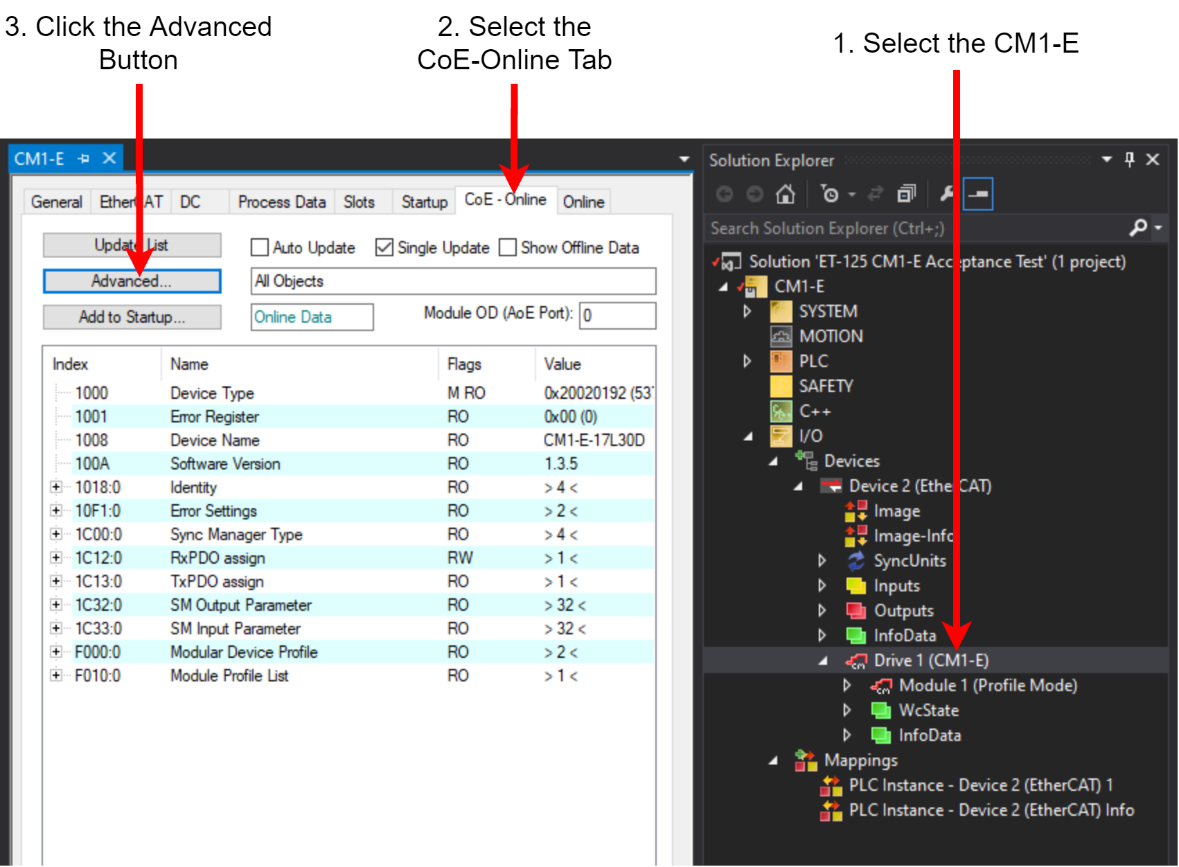
The following instructions show how to read/write the objects in TwinCAT3 through the online object dictionary. It assumes a CM1-E drive has already been added.
-
In the Solution Explorer select the CM1-E drive
-
Select the CoE-Online tab. Only the objects listed in the EDS are currently listed.
-
Click the Advanced button to enable reading all objects.
-
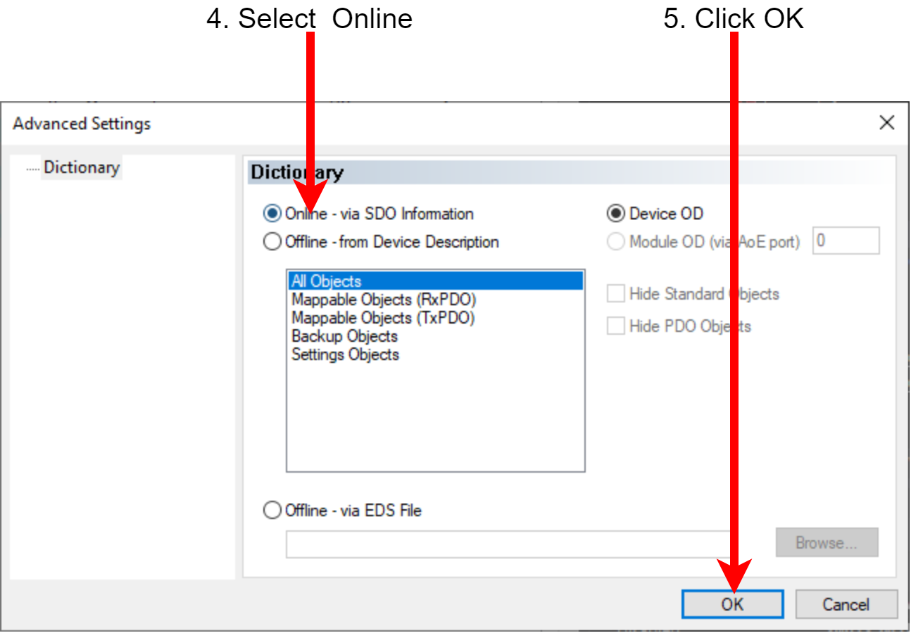
Select the Online radio button
-
Click OK
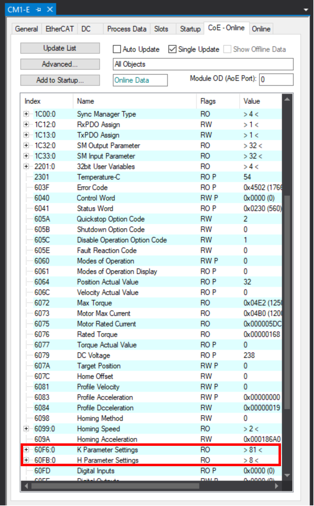
The full object dictionary is now available. The K and H parameters are shown below in red. Expand the list to see all the parameters.