Output Functions
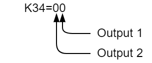
Output 1 and output 2 are assigned values as follows on K34:
| Value | Function | Description |
|---|---|---|
| 0 | AO2 - Analog Output | Write to the analog output using a variable assigned to "AO2" |
| 1 | In Position | Output indicate the motors In Position status |
| 2 | Alarm | Output is asserted when the motor is in an alarm state |
| 3 | O1/F1 | Only applicable to OUT1. Use O1 and F1 to manually switch OUT1 on/off |
| 4 | O2/F2 | Only applicable to OUT2. Use O2 and F2 to manually switch OUT2 on/off |
| 5 | Analog Output | Analog output value is set by K35 |
| 6 | Merge Motion | Digital output is asserted when a merge motion is executed |
| 7 | Quadrature/Index Output | OUT1 and OUT2 are combined to output a quadrature signal tracking the motors position |
| 8 | Motor Free | Digital output indicates whether is in a motor free state or not |
| 9 | Push Mode Torque Limit Reached | Digital output is asserted when the push mode torque limit is reached |
Default: K34=21
AO2
AO2 will only work on output 2. Programming output 2 as AO2 will set output 2 to analog and allow you to control the analog value of the output via a variable programmed as “AO2”. The valid range for this variable is 0 to 255, corresponding to 0VDC to 5VDC. To use the Analog output variable, K34 must be set to 0.
In Position
The In Position Output type will activate whenever the motor status is “Ux=8”, which means that the motor has reached its target position and is in the ready state. Any errors or change in status will deactivate this output.
Alarm
The Alarm output will activate whenever the motor is in an alarmed state. The alarmed state refers to any error status on the motor which will cause the motor to disable. This includes over load, over speed, and position error overflow errors. This output will not activate if the motor is manually disabled nor if an emergency stop is triggered.
CML O1/F1
This function will only operate on output 1. By programming output 1 as CML O1/F1, the output can be manually controlled by sending the O1 command to turn on output 1 or the F1 command to turn off output 1. These commands can be sent either manually via the serial communications, or they can also be added to a program or logic bank to execute at a specified time.
CML O2/F2
This function is the same as the O1/F1 command, but will only operate on output 2.
Analog Output
By programming the output as analog output, it will be an analog voltage output which will behave as programmed in parameter K35. The range of output voltages on the analog output is 0VDC to 5VDC as measured between the OUT and +5V terminals.
Merge Motion
When using a merge motion command, the merge motion output will activate when the motor passes by a target position and is on the way to the next passing point. The length of the output pulse is determined by parameter K73.
Quadrature/Index Output
The quadrature output can be used with dual outputs as a quadrature signal or as single outputs giving an index output.
The following additional K parameters are used when setting up the quadrature/index output
| Parameter | Name | Description |
|---|---|---|
| K24 | Output Interval (pulses) | K24 sets the value of the quadrature interval
Example: K24=100 will output a full wave form on OUT1 and OUT2 for each 100 pulses the motor moves. |
| K33 | Invert Output | K33 inverts the output.
|
| K54 | Quadrature Interval Offset (pulses) | K54 sets an optional offset which shifts that phase of each output by the offset amount. |
Quadrature Output
K34=77 must be set to have both outputs generate a quadrature signal. The diagram below shows the individual output signals and their timing
Index Output
If either OUT1 or OUT2 are set to 7 in K34 they will output an index signal based on the motor's position. As seen in the above diagram:
- OUT1 signal is inline with 0
- OUT2 signal is phase shifted by 90°
K54 - Phase Shift
K54 can be used to shift the signal by the number of pulses in K54,
Motor Free
The motor free output activates whenever the motor is disabled. This can be either from being manually disabled, or from an error or alarm state which caused the motor to disable itself. This output will deactivate when the motor is re-enabled.
Push Mode Torque Limit Reached
This output will activate whenever you are using a push move, and the torque limit programmed in K80 is reached. The output will deactivate when the push time programmed in K61 expires and the push move ends.
Overview
Content Tools