IN1 and IN2 on the motor are photo-coupled and can be connected in either a sinking or sourcing configuration. IN3 and IN4 are sourcing inputs, and IN4 can also be configured to act as an analog voltage input.
Input Specifications
Digital Inputs 1 & 2 | Minimum | Maximum | Unit |
|---|---|---|---|
Voltage Range | 0 | 24 | VDC |
Low Level | 0 | 0.8 | VDC |
High Level | 2.4 | 24 | VDC |
Operating Current | 7 | 15 | mA |
Switching Frequency | - | 500 | KHz |
Pulse Width | 0.8 | - | µs |
Serial UART | Minimum | Maximum | Unit |
|---|---|---|---|
Voltage Range | 0 | 5 | VDC |
Communication Speed | 9600 | 512000 | bps |
Digital Inputs 3 & 4 | Minimum | Maximum | Unit |
|---|---|---|---|
Voltage Range | 0 | 5 | VDC |
Low Level | 0 | 0.8 | VDC |
High Level | 2.4 | 5 | VDC |
Operating Current | 7 | 15 | mA |
Switching Frequency | - | 833 | Hz |
Pulse Width | 10 | - | ms |
| Analog IN4 | Minimum | Maximum | Unit |
|---|---|---|---|
| Voltage Range | 0 | 5 | VDC |
| A/D Resolution | - | 10 | bits |
| Numerical Resolution | 0 | 1023 | - |
Input Wiring
IN1 and IN2
IN1 and IN2 can be configured as either sinking or sourcing inputs. They will function as long as the appropriate voltage is seen between the IN+ and IN- Terminals. The following examples utilize a push button to act as the input trigger. In reality this push button would often be replaced by an output from another device, such as a PLC, or other controller. IN1 and IN2 can operate at voltages up to 24VDC. Any of the below examples showing IN1 are also true for IN2.
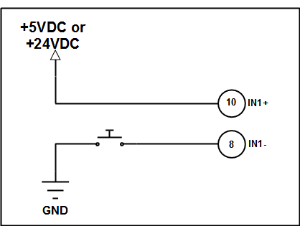
IN1 as a Sourcing Input
draw
Fig. 1 - IN1 as a Sourcing Input
IN1 and IN2 can be configured as either sinking or sourcing inputs. They will function as long as the appropriate voltage is seen between the IN+ and IN- Terminals. The following examples utilize a push button to act as the input trigger. In reality this push button would often be replaced by an output from another device, such as a PLC, or other controller. IN1 and IN2 can operate at voltages up to 24VDC. In Fig.1, a push button is used to connect the negative side of IN1 to ground. Since the positive side of IN1 is connected to the positive voltage source, this results in the activation of IN1.
IN1 as a Sinking Input
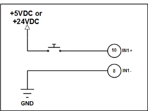
Fig. 2 - IN1 as a Sinking Input
In Fig.2, a push button is being used to connect the positive side of IN1 to the +5VDC supply from the motor. Since the negative side of the input is connected to the ground, this results in the activation of IN1.
IN3 and IN4
IN3 and IN4 are both 0V inputs. They have an internal 4.7K pullup resistor to 5VDC. They can tolerate a maximum of 5V.
IN3 connected to a Push Button
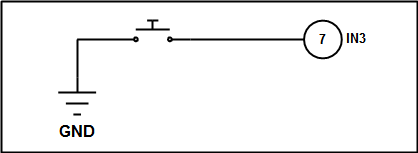
Fig.3 IN3 using a Push Button
The example in Fig.3 illustrates using a push button to connect the input to ground to activate IN3.
Analog Input
IN4 on the cool muscle can be configured to act as an analog input. This analog input has a working voltage of 0-5VDC and a ten bit resolution. This means that the digital conversion reading you get from the motor will be a value from 0 to 1023. This gives an effective resolution of about 204 counts per volt. For instance, if you have an analog voltage of 2VDC applied to the input, you should see corresponding value in the motor of about 408.
Analog Input Wiring
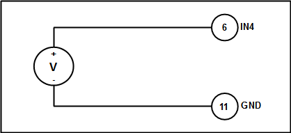
Fig.4 - Analog Input Wiring
The analog voltage source should be wired between the IN4 terminal, and the Ground terminal, as showing in Fig. 4.
Setting the Analog Input to a Variable
We can obtain the digital conversion of the analog value directly by setting a variable in the V register as “AIN4”, for example V2.1=”AIN4” will set variable 2 in motor 1 to be equal to the current analog input value. This will allow us to grab that value and we can then perform mathematical operations or compare it in order to achieve more complex results.
Analog Speed and Position Control
It is possible to configure the analog input on the Cool Muscle to directly control speed or position without having to write a program. There are five parameters which will affect this behavior:| Parameter | Description |
|---|---|
| K38 | Analog Interface (Set speed or position control) |
| K39 | Voltage Filter Gain |
| K40 | Max Speed (only used for speed control) |
| K41 | Travel Range (only used for position control) |
| K64 | Analog Input Function |
The parameter K64 allows us to set a number of different functions for the analog input. For instance, we can have register P25 always equal to the analog input value, or use the analog input as a multiplier for position values. In order to use the speed and position control, we set K64=9. This sets the analog input to analog control only mode. Once we have done this, we set K38. If K38=0 we are using speed control, if K38=1 we are using position control.
The next step is to set our limits. If we are using speed control, we will set our max speed value in K40 in RPM. For example, if we set K40=300 the motors speed would vary from 0RPM to 300RPM when the analog input voltage varies from 0VDC to 4.8VDC respectively.
If we are using position control, we set the max travel range in K41 in pulses. This means that if we set K41=1000, the motors position would vary from 0pulses to 1000pulses as the analog input voltage varies from 0VDC to 4.8VDC respectively.
The final parameter to set would be K39. This is a voltage filter. You will use this if there is lots of ripple or bounce in your analog signal that you don’t want the motor to respond to. The higher the value of K39, the less sensitive the analog input will be to small disturbances.
Input Activation
There are six methods for activating an input: Logical high quick response, logical high slow response, quick response rising edge, quick response falling edge, slow response rising edge, and slow response falling edge. These can all be used in conjunction with one another simultaneously. This means that you could have one input doing six different things depending on these conditions.
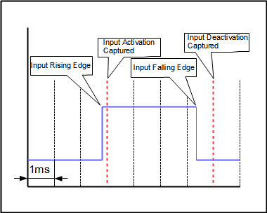
Fig. 5 - Quick Response Input Activation
Quick Response
For the quick response conditions, the inputs are scanned every 1ms. This means that when the input is triggered, there is a maximum of 1ms before the input will register as activated within the motor, depending on where in the scanning cycle it is triggered. Likewise, when the input is shut off, there is a maximum of 1ms before the input will register as deactivated within the motor. The quick response logical high, rising edge, and falling edge functions are programmed in parameters K27, K28, and K29 respectively. Fig. 5 demonstrates the input activation cycle for the quick response input.
Slow Response
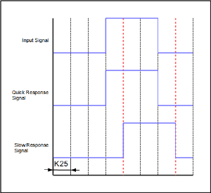
Fig. 6 - Slow Response Input Activation
The slow response conditions are triggered at a programmable delay after the quick response is triggered. The delay can be found in parameter K25. For example, if the delay is programmed for 0.2sec in K25, when the input is activated, the quick response will trigger withing the next 1ms, and the slow response functions will trigger 0.2sec after that.
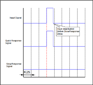
Fig. 7 - Slow Response Input not Recognized
If the Input is deactivated before the slow signal response time is reached, only the quick response function is triggered and the slow response is not recognized.
Overview
Content Tools