
TCP/UDP
Connections and Ports
Any TCP/IP enabled client device can connect and communicate with the CM1-T. The table below lists the ports and protocols they are associated with
Protocol | Port # | # TCP | # UDP | Description |
|---|---|---|---|---|
10001 | 1 | 1 | Protocol used by the standard motor. Program the motor to run from IO, etc. | |
10002 | 1 | 1 | Directly control the motor in a number of modes such as position, speed and torque
| |
502 | 1 | 0 | Modbus access to all motor registers including CML and Direct Control.
| |
30718 | 0 | 1 |
| |
44818 | 2 | 1 | EtherNet/IP CIP
|
This section focus on the Direct Control Port and the Motor Information port. For information on the other protocols go to their specific section.
Direct Control Port
Port 10002 can be used to read and write the Direct Control registers. TCP/IP or UDP can be used.
Write Data Packet
This is the data received by the motor on a write from the TCP/UDP Client.
TCP/IP or UDP
Port 10002
Length = 28 bytes
Data
Byte | Register | Size/Type | Description |
|---|---|---|---|
0-3 | TargetPosition | DINT | Final target position |
4-7 | TargetSpeed | DINT | Maximum targetspeed |
8-9 | TargetTorque | INT | Maximum torque |
10-11 | TargetAccelertion | INT | Acceleration (used when accelerating to target speed) |
12-13 | TargetDeceleration | INT | Deceleration (used when stopping) |
14-15 | Controlword | INT | Control the motor operation |
16 | ModeOfOperation | SINT | Set the required mode of operation |
17 | DigitalOUT | SINT | Set the 2 digital outputs. Requires K34=44. |
18-19 | WriteAddress1 | INT | Address of the motor register to write to |
20-23 | WriteValue1 | DINT | Value to be written to the motor register |
24-25 | ReadAddress1 | INT | Address of the motor register to read |
26-27 | PAD | INT | 16-bit padding not used |
Read Data Packet
This is the data transmitted by the motor to the TCP/UDP Client when a write packet is received
TCP/IP or UDP
Port 10002
Length = 36 bytes
Data
Byte | Register | Size/Type | Description |
|---|---|---|---|
0-3 | us50Counter | DINT | CPU clock time in 50us counts |
4-7 | ActualPosition | DINT | The actual position of the motor in encoder counts |
8-11 | MotionTarget | DINT | The actual instantaneous position the motor is currently moving to. |
12-15 | ActualSpeed | DINT | Actual speed of the motor in encoder counts/s |
16-17 | MotorStatus | INT | The motors status (error, homing, in position, etc) |
18-19 | PercentActualCurrent | INT | Percentage (0.1%) of rated current. 1000 = rated, 1100 = peak. |
20-21 | PercentOverloadTorque | INT | Percentage (0.1%) of overload torque. |
22-23 | AnalogIN | INT | 10 bit analog input value (0-1023) |
24-25 | DCVoltage | INT | 24V DC bus voltage in 0.1V |
26 | DigitalIN | SINT | Digital IN status. B0-B3 = IN1-IN4 |
27 | Temperature | SINT | Drive temperature in ºC |
28 | ModeOfOperationDisplay | SINT | Indicates the mode of operation currently set |
29 | ErrorCode | SINT | Error code on communication error |
30-31 | ReadAddress1 | INT | Address of the motor register for ReadValue1 |
32-35 | ReadValue1 | DINT | The value in the motor register displayed in ReadAddress1 |
Motor Information Port
The motor information port is used to query the motor configuration data as well as all status data. The status data can also be set to stream out at defined time intervals.
Port 30718
UDP only
The motor receives a 4 byte data packet which indicates the type of request. The response includes a 4 byte header. The request and expected response header are defined as such:
Command | B3 (Command ID) | B2 | B1 | B0 | |
|---|---|---|---|---|---|
1 | Configuration Request | 0xF6 | 0x00 | 0x00 | some data |
Configuration Response | 0xF7 | 0x00 | 0x00 | echo some data | |
2 | Information Request | 0xF4 | Time ms high byte | Time ms low by | some data |
Information Response | 0xF5 | Counter high byte | Counter low byte | echo some data |
Configuration Data
The configuration data responds with info regarding the motor's network configuration, firmware versions and serial number
To request the configuration data send the following data packet
Byte | Value | Description |
|---|---|---|
0 | 0x00-0xFF | Any value. This will be echoed back on the response |
1 | 0x00 | Ignored |
2 | 0x00 | Ignored |
3 | 0xF6 | Command ID for configuration request |
The response packet is returned as follows
Bytes | Description |
|---|---|
0 | Echo of some data |
1-2 | 0x0000 |
3 | 0xF7 (Command ID) |
4-11 | N/A |
12-15 | Current IP Address |
16-19 | Subnet Mask |
20-23 | Gateway IP |
24-29 | MAC Address |
30 | DHCP Enabled |
31 | N/A |
32-35 | CM1-T Interface Firmware Version |
36-39 | CM1 Drive Firmware Version |
40-99 | Part Number (ascii) |
100-103 | Reserved |
104-105 | Production Date |
106-107 | Product ID |
108-109 | Serial Number |
110-118 | CM1-T Interface Hardware Version |
119 | Reserved |
Information Data
The information request returns a complete set of the motor's state data including, position, speed, drive status, IO, etc
Send Data
To request the information data send the following data packet:
length = 4 bytes
Byte | Value | Description |
|---|---|---|
0 | 0x00-0xFF | Any value. This will be echoed back on the response |
1 | 0x00 | Interval Time in ms low byte |
2 | 0x00 | Interval Time in ms high byte |
3 | 0xF4 | Command ID for information request |
Interval Time
The Interval Time is a 16 bit value that sets the response interval in ms. It has the following characteristics
Value range: [0-65536]
If value = 0 then the query sends a single response
If value > 0 then a response is sent at the interval time
Receive Data
The following data is received on a request or on an interval response
length = 33 bytes
Byte | Name | Description |
|---|---|---|
0 | Data echo | Echo the data sent in B0 of the request |
1-2 | Counter Value | Each response increments the counter value. A query resets the counter. |
3 | 0xF5 - Command ID | Response command ID is 0xF5 |
4-7 | CPUTime | CPU clock time in 50us counts |
8-11 | ActualPosition | The actual position of the motor in encoder counts |
12-15 | ActualTargetPosition | The actual instantaneous position the motor is currently moving to. |
16-17 | MotorStatus | The motors status (error, homing, in position, etc) |
18-19 | ActualRatedCurrent | Percentage (0.1%) of rated current. 1000 = rated, 1100 = peak. |
20-21 | ActualOverloadTorque | Percentage (0.1%) of overload torque. |
22-23 | AnalogIN | 10 bit analog input value (0-1023) |
24 | DigitalIN | Digital IN status. B0-B3 = IN1-IN4 |
25 | Temperature | Drive temperature in ºC |
26-27 | DCVoltage | 24V DC bus voltage in 0.1V |
28 | DigitalOUT | Digital OUT status. B0-B1 = OUT1-OUT2 |
29 | Reserved | - |
30 | ModeOfOperationDisplay | Indicates the mode of operation currently set |
31 | ActualSpeed | Actual speed of the motor in encoder counts/s |
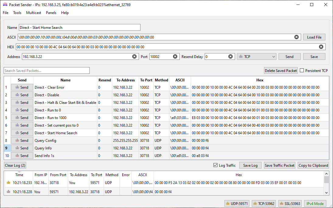
Example Packets
The following example uses Packet Sender to execute some direct moves, query configuration and query information.
Please be aware of any firewall restrictions especially when using UDP.
Name | Send Data Bytes |
|---|---|
Direct - Clear Error | 00 00 00 00 10 00 00 00 4C 04 64 00 64 00 20 00 03 00 00 00 00 00 00 00 00 00 00 00 |
Direct - Disable | 00 00 00 00 10 00 00 00 4C 04 64 00 64 00 10 00 03 00 00 00 00 00 00 00 00 00 00 00 |
Direct - Halt & Clear Start Bit & Enable | 00 00 00 00 10 00 00 00 4C 04 64 00 64 00 02 00 03 00 00 00 00 00 00 00 00 00 00 00 |
Direct - Run to 0 | 00 00 00 00 10 00 00 00 4C 04 64 00 64 00 01 00 03 00 00 00 00 00 00 00 00 00 00 00 |
Direct - Run to 1000 | E8 03 00 00 10 00 00 00 4C 04 64 00 64 00 01 00 03 00 00 00 00 00 00 00 00 00 00 00 |
Direct - Set current pos to 0 | 00 00 00 00 10 00 00 00 4C 04 64 00 64 00 40 00 03 00 00 00 00 00 00 00 00 00 00 00 |
Direct - Start Home Search | 00 00 00 00 10 00 00 00 4C 04 64 00 64 00 80 00 03 00 00 00 00 00 00 00 00 00 00 00 |
Query Config | 00 00 00 f6 |
Query Info | 00 00 00 f4 |
Query Info 1s | 00 e8 03 f4 |
Direct - Run uses a speed = 10, acceleration = 100, deceleration = 1000 and Torque = 1100.
The image below shows Packet Sender with the response to Query Info
The Packet Sender database for the above example can downlaoded here - CM1-T Example.ini