
EtherNet/IP
Introduction
This section explains how to use the CM1-T Cool Muscle motor with EtherNet/IP. It is assumed there is a basic knowledge of EtherNet/IP and PLC programming. The implementation makes use of the different Direct Control in the motor. It does not use CML logic and bank programming. However, setup (K) and controller gain (H) parameters are used for things like motor resolution, s-curve, software limits, etc. These are all accessible to be setup with Control Room or over explicit messages.
Device Profile
The CM1-T uses a generic device profile. This is to allow it to be flexible and operate in a number of operation modes.
Direct Control Operation
This mode enables the PLC to directly control the motor. See Direct Control on how to use the I/O messages to control the motor. Add on instructions are supplied in the downloads section.
CML Operation
This mode lets to motor control itself through CML programming. The PLC reads and writes to registers to monitor and make changes how the motor operates.
I/O Messages
There are two distinct I/O Assemblies based on the operation mode required.
Direct Control Operation
I/O | Assembly Instance | Size |
|---|---|---|
Input | 100 | 36 |
Output | 112 | 28 |
Configuration | 1 | 0 |
T2O (Input) Message
Instance = 100
Size = 36 bytes
Byte | Name | Data Type |
|---|---|---|
0-3 | us50Counter | DINT |
4-7 | ActualPosition | DINT |
8-11 | MotionTarget | DINT |
12-15 | ActualSpeed | DINT |
16-17 | MotorStatus | INT |
18-19 | PercentActualCurrent | INT |
20-21 | PercentOverloadTorque | INT |
22-23 | AnalogIN | INT |
24-25 | DCVoltage | INT |
26 | DigitalIO | SINT |
27 | Temperature | SINT |
28 | ModeOfOperationDisplay | SINT |
29 | ErrorCode(1) | SINT |
30-31 | ReadAddress1 | INT |
32-35 | ReadValue1 | DINT |
(1) - ErrorCode is currently reserved and returns 0. Use MotorStatus to get motor error information
O2T (Output) Message
Instance = 112
Size = 28
Byte | Name | Data Type |
|---|---|---|
0-3 | TargetPosition | DINT |
4-7 | TargetSpeed | DINT |
8-9 | TargetTorque | INT |
10-11 | TargetAccelertion | INT |
12-13 | TargetDeceleration | INT |
14-15 | Controlword | INT |
16 | ModeOfOperation | SINT |
17 | DigitalOUT | SINT |
18-19 | WriteAddress1 | INT |
20-23 | WriteValue1 | DINT |
24-25 | ReadAddress1 | INT |
26-27 | PAD | INT |
CML Operation
I/O | Assembly Instance | Size |
|---|---|---|
Input | 101 | 60 |
Output | 113 | 44 |
Configuration | 1 | 0 |
T2O (Input) Message
Instance = 101
Size = 60 bytes
Byte | Name | Data Type |
|---|---|---|
0-3 | us50Counter | DINT |
4-7 | ActualPosition | DINT |
8-11 | MotionTarget | DINT |
12-15 | ActualSpeed | DINT |
16-17 | MotorStatus | INT |
18-19 | PercentActualCurrent | INT |
20-21 | PercentOverloadTorque | INT |
22-23 | AnalogIN | INT |
24-25 | DCVoltage | INT |
26 | DigitalIO | SINT |
27 | Temperature | SINT |
28 | ModeOfOperationDisplay | SINT |
29 | ErrorCode(1) | SINT |
30-31 | ReadAddress1 | INT |
32-35 | ReadValue1 | DINT |
36-37 | ReadAddress2 | INT |
38-39 | ReadAddress3 | INT |
40-41 | ReadAddress4 | INT |
42-43 | ReadAddress5 | INT |
44-47 | ReadValue2 | DINT |
48-51 | RadValue3 | DINT |
52-55 | ReadValue4 | DINT |
56-59 | ReadValue5 | DINT |
(1) - ErrorCode is currently reserved and returns 0. Use MotorStatus to get motor error information
O2T (Output) Message
Instance = 113
Size = 44
Byte | Name | Data Type |
|---|---|---|
0-3 | WriteValue1 | DINT |
4-7 | WriteValue2 | DINT |
8-11 | WriteValue3 | DINT |
12-15 | WriteValue4 | DINT |
16-19 | WriteValue5 | DINT |
20-21 | WriteAddress1 | INT |
22-23 | WriteAddress2 | INT |
24-25 | WriteAddress3 | INT |
26-27 | WriteAddress4 | INT |
28-29 | WriteAddress5 | INT |
30-31 | ReadAddress1 | INT |
32-33 | ReadAddress2 | INT |
34-35 | ReadAddress3 | INT |
36-37 | ReadAddress4 | INT |
38-39 | ReadAddress5 | INT |
40 | DigitalOUT | SINT |
41 | PAD | SINT |
42-43 | PAD | INT |
Read/Write Motor Registers
In the I/O messages there is the ability to read and write to internal motor registers. These registers could be configured as flags, input counters, or other custom operations.
Direct Operation has
1 x read register
1 x write register
CML Operation has
5 x read registers
5 x write registers
The register addresses can be changed after a cycle to read/write to more than 1 register.
Register Address
The register address is coded into a 2 byte (UINT16) format as follows
B1 | B0 |
|---|---|
Register Type (P, S, A, V, etc) | Register Number (0 to max) |
Register Address = Register Type Register Number
The following list maps the register type and the applicable number range
B1 Value (hex) | Register | Register No. Range | Example | ||
|---|---|---|---|---|---|
Register | Address | ||||
Hex | Decimal | ||||
16#00 | N/A | N/A | - | - | - |
16#01 | reserved | reserved | - | - | - |
16#02 | reserved | reserved | - | - | - |
16#03 | P | 0-25 | P0 | 16#0300 | 768 |
16#04 | S | 0-15 | S1 | 16#0x0401 | 1025 |
16#05 | A | 0-8 | A5 | 16#0x0505 | 1285 |
16#06 | T | 0-8 | T2 | 16#0x0602 | 1538 |
16#07 | M | 0-8 | M0 | 16#0x0700 | 1792 |
16#08 | R | 0-25 | R16 | 16#0x0810 | 2064 |
16#09 | N | 0-25 | N15 | 16#0x090F | 2319 |
16#0A | V | 0-15 | V10 | 16#0x0A0A | 2570 |
For a complete list go to EtherNet/IP#Complete Register Address Map
Explicit Messages
K Parameters - Setup Parameters
Get Attribute Single - Service Code 0x0E
Set Attribute Single - Service Code 0x10
Class | 0x64 |
|---|---|
Instance | 1 |
Attribute | The attribute represents the K number. example: K37 → 37d → 0x25 |
H Parameters - Gain Parameters
Get Attribute Single - Service Code 0x0E
Set Attribute Single - Service Code 0x10
Class | 0x65 |
|---|---|
Instance | 1 |
Attribute | H0 → 0x01 |
Direct Control Operation
Control Modes
This section focuses on controlling the motor with the provided Add on Instructions (AOIs). These will satisfy most applications, however, if required, the motor can be controlled by setting the CM1-T objects directly (see I/O Messages). Understanding the Direct Control will be important in this case.
There are currently 3 main control modes available while running the motor over EtherNet/IP.
Position - this mode sets the motor to run to a target position. The position could be absolute or relative
Speed - this mode allows the motors speed to be controlled for continuous motion
Torque - this mode allows the motors torque to be controlled.
The control modes are mapped to the ModeOfOperation value from the CM1T_ControlMode AOI:
Control Mode | CM1T_ControlMode AOI value | O2T ModeOfOperation Value |
|---|---|---|
Position | 0 | 3 |
Speed | 1 | 3 |
Torque | 2 | 11 |
In addition:
Homing is an additional mode that can be executed at any point. Homing should start from a known safe state to avoid unexpected changes in motion
All modes can be switched to during motion. It is recommended the state is switched during a known safe state.
Torque can be limited in all modes. Running in torque mode will disable errors such as position error which can still occur in other modes if the set torque is too low. The torque is set in 0.1% of rated torque. The range is [0,1100]. By default the torque is set to 1100 when using the AOIs supplied.
All modes use common objects such as position, speed, torque, acceleration and controlword. Switching parameters in another mode will change the value in the existing mode.
Setting the Start bit to 0 will NOT halt motion. The HALT bit must be used to interrupt motion.
Position Mode
Absolute position and relative position both use the position mode. The key difference in operation between the two is the usage of the start bit in the CM1T_Controlword. An absolute move will accept a new position immediately if the start bit is 1.
Start Bit Usage
BIT | Name | Value | Description |
|---|---|---|---|
B0 | Start/New Set Point | 0 |
|
0 → 1 |
| ||
1 | Execute any changes in any of the profile registers immediately. |
Motion Parameters
Position moves will accept the following motion parameters. These will be processed immediately if the start bit is high.
Name | Unit | Data Type | Access |
|---|---|---|---|
PositionTarget | counts | DINT | AOI(2) or Axis tag |
SpeedTarget | counts/s | DINT | AOI or Axis tag |
AccelerationTarget | 1000 counts/s2 | INT | AOI or Axis tag |
DecelerationTarget(1) | 1000 counts/s2 | INT | AOI or Axis tag |
TorqueTarget | 0.1% rated torque | INT | Axis Tag |
(1) If the deceleration is set to 0 the acceleration value will be used
(2) MoveAbsolute or MoveRelative AOI
Speed Mode
A speed move has no target position and will continue to run at the target speed. Setting a -ve speed value will reverse direction.
Start Bit Usage
BIT | Name | Value | Description |
|---|---|---|---|
B0 | Start/New Set Point | 0 |
|
0 → 1 |
| ||
1 | Execute any changes in any of the profile registers immediately. |
Motion Parameters
Speed moves will accept the following motion parameters. These will be processed immediately if the start bit is high.
Name | Unit | Data Type | Access |
|---|---|---|---|
SpeedTarget | counts/s | DINT | AOI(2) or Axis tag |
AccelerationTarget | 1000 counts/s2 | INT | AOI or Axis tag |
DecelerationTarget(1) | 1000 counts/s2 | INT | AOI or Axis tag |
TorqueTarget | 0.1% rated torque (1) | INT | Axis Tag |
(1) If the deceleration is set to 0 the acceleration value will be used
(2) MoveSpeed AOI
Torque Mode
A torque move only uses a target torque and maximum speed. Acceleration of the motor should be limited by adjusting the target torque or speed.
Setting a -ve torque value will reverse direction.
Start Bit Usage
BIT | Name | Value | Description |
|---|---|---|---|
B0 | Start/New Set Point | 0 |
|
0 → 1 |
| ||
1 | Execute any changes in any of the profile registers immediately. |
Motion Parameters
Torque moves will accept the following motion parameters. These will be processed immediately if the start bit is high.
Name | Unit | Data Type | Access |
|---|---|---|---|
SpeedTarget | counts/s | DINT | AOI(1) or Axis tag |
TorqueTarget | 0.1% rated torque Range: ± 1100 Where:
| INT | AOI or Axis Tag |
(1) MoveTorque AOI
General Resources
EDS File
The CM1-T EtherNet/IP eds file can be found on the Datasheets and Downloads page.
CM1-T Library
The CM1-T Library for use with Codesys, Schneider, Beckhoff, Wago and other IEC 61131-3 PLCs can be found on the Datasheets and Downloads page.
RSLogix Resources
See Datasheets and Downloads to download the UDTs, AOIs and sample program.
User Data Types
Direct Control Operation
CM1T_Axis
The CM1-T_Axis data type defines how the bytes are assigned withing the IO message.
Name | Data Type | Description |
|---|---|---|
Input | SINT[36] | Data coming from the CM1-T |
Output | SINT[28] | Data going to the CM1-T |
us50Counter | DINT | Motor 50us counter |
ModeOfOperation | SINT | Select control mode |
ModeOfOperationDisplay | SINT | Current control mode |
Controlword | CM1T_Controlword | Control operation |
DriveStatus | CM1T_DriveStatus | Drive status |
PositionTarget | DINT | Target position for position move |
SpeedTarget | DINT | Max speed for target move |
TorqueTarget | INT | Max torque for target move |
AccelerationTarget | INT | Acceleration for target move |
DecelerationTarget | INT | Deceleration for target move |
PositionActual | DINT | Actual position of the motor |
TargetActual | DINT | 1ms target position of the motor |
PositionError | DINT | Error between actual and target |
SpeedActual | DINT | Actual speed of the motor |
CurrentActual | INT | Actual current percentage of the motor (0.1% rated) |
OverloadActual | INT | 0.1% of overload torque |
DCVoltage | INT | 24V DC input value at 0.1V |
AnalogIN | INT | 10bit analog input (0-1023) |
DigitalIN | SINT | Read digital inputs |
DigitalOUT | SINT | Set digital outputs |
Temperature | SINT | Drive temperature in °C |
ErrorCode | SINT | ErrorCode is currently reserved and returns 0. |
ReadAddress1 | INT | Address of register to read |
ReadValue1 | DINT | Value of read register |
ReadValueAddress1 | INT | Address of the current read register |
WriteValue1 | DINT | Register write value |
WriteRegister1 | INT | Write register address |
CM1T_Controlword
Name | Data Type | Description |
|---|---|---|
Start | BOOL | Start/New set point |
Halt | BOOL | Halt current motion |
Relative_Move | BOOL | Execute position move as relative |
Speed_Control | BOOL | Execute move as a speed only move |
Disable | BOOL | Disable the drive |
Reset_Error | BOOL | Reset error with rising edge |
Set_to_Zero | BOOL | Set the current position to zero with rising edge |
Home | BOOL | Home the motor with rising edge |
CM1T_DriveStatus
Name | Data Type | Description |
|---|---|---|
StatusValue | SINT | Motor status and error type |
StatusValue1 | SINT | Additional motor status |
In_Position | BOOL | Motor is in position and ready to move |
Moving | BOOL | Motor is currently moving |
Disabled | BOOL | Drive is disabled |
Error | BOOL | Drive is in error state |
MoveComplete | BOOL | Move is completed |
NewStartRequired | BOOL | Rising edge required to restart motion |
HomeAchieved | BOOL | Homing has been achieved |
CML Operation
CM1T_CMLAxis
The CM1-T_CMLAxis data type defines how the bytes are assigned withing the IO message.
Name | Data Type | Description |
|---|---|---|
Input | SINT[60] | Data coming from the CM1-T |
Output | SINT[44] | Data going to the CM1-T |
us50Counter | DINT | Motor 50us counter |
DriveStatus | CM1T_DriveStatus | Drive status |
PositionActual | DINT | Actual position of the motor |
TargetActual | DINT | 1ms target position of the motor |
PositionError | DINT | Error between actual and target |
SpeedActual | DINT | Actual speed of the motor |
CurrentActual | INT | Actual current percentage of the motor (0.1% rated) |
OverloadActual | INT | 0.1% of overload torque |
DCVoltage | INT | 24V DC input value at 0.1V |
AnalogIN | INT | 10bit analog input (0-1023) |
DigitalIN | SINT | Read digital inputs |
DigitalOUT | SINT | Set digital outputs |
Temperature | SINT | Drive temperature in °C |
ErrorCode | SINT | (1) - ErrorCode is currently unused and returns 0. Use MotorStatus to get motor error information |
WriteValue | DINT[5] | Register write value (array) Address of register to read |
ReadValue | DINT[5] | Value of read register (array) |
WriteAddress | INT[5] | Write register address (array) |
ReadAddress | INT[5] | Read address register (array) |
ReadValueAddress | INT[5] | Address of the current returned read register (array) |
CM1T_CMLDriveStatus
Name | Data Type | Description |
|---|---|---|
StatusValue | SINT | Motor status and error type |
StatusValue1 | SINT | Additional motor status |
In_Position | BOOL | Motor is in position and ready to move |
Moving | BOOL | Motor is currently moving |
Disabled | BOOL | Drive is disabled |
Error | BOOL | Drive is in error state |
HomeAchieved | BOOL | Homing has been achieved |
Add-On Instructions
Direct Control Operation
The following tables outlines the available add-on instructions
Name | Description | Required |
|---|---|---|
CM1T_DataExchange | Exchanges data between the drive and the drive variable | Yes |
CM1T_Enable | Enables the motor | No |
CM1T_Disable | Disables the motor | No |
CM1T_ClearFault | Clears any faults on the drive | No |
CM1_TControlMode | Set the type of control mode required | No |
CM1T_MoveAbsolute | Executes an absolute position move | No |
CM1T_MoveRelative | Executes a relative position move | No |
CM1T_MoveSpeed | Executes a speed move | No |
CM1T_MoveTorque | Executes a torque move | No |
CM1T_MoveHome | Executes a home routine | No |
CM1T_ReadRegister | Read a motor register value | No |
CM1T_WriteRegister | Write a value to a motor register | No |
CM1T_DataExchange
This AOI is required if any other AOIs are used. One instance is required for each CM1-T axis being controlled.
It has a number of functions
It exchanges data between the motor connections and the motor/drive tag.
It places the Controlword bits into the Controlword data type
It retrieves the drive status and places it into the DriveStatus variable.
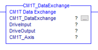
Parameters
Operand | Type | Format | Description |
|---|---|---|---|
CM1T_DataExchange | CM1T_DataExchange | Tag | Instance tag for the AOI |
DriveInput | AB:ETHERNET_MODULE_SINT_32Bytes:I:0 | Tag | Module defined connection input for the CM1-T |
DriveOutput | AB:ETHERNET_MODULE_SINT_20Bytes:O:0 | Tag | Module defined connection output for the CM1-T |
CM1T_Axis | CM1T_Axis | Tag | Working tag for the CM1-T axis |
Execution
Condition | Action |
|---|---|
Prescan |
|
Rung Condition - TRUE |
|
Rung Condition - FALSE | N/A - rung-condition-out is set to false |
CM1T_Enable
This AOI enables the motor and drive. Torque will be present.
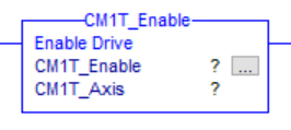
Parameters
Operand | Type | Format | Description |
|---|---|---|---|
CM1T_Enable | CM1T_Enable | Tag | Instance tag for the AOI |
CM1T_Axis | CM1T_Axis | Tag | Working tag for the CM1-T axis |
Execution
Condition | Action |
|---|---|
prescan | N/A - rung-condition-out is set to false |
rung-condition-in is true |
|
rung-condition-in is false | N/A - rung-condition-out is set to false |
CM1T_Disable
This AOI disables the motor and drive. Torque will not be present
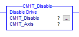
Parameters
Operand | Type | Format | Description |
|---|---|---|---|
CM1T_Disable | CM1T_Disable | Tag | Instance tag for the AOI |
CM1T_Axis | CM1T_Axis | Tag | Working tag for the CM1-T axis |
Execution
Condition | Action |
|---|---|
prescan | N/A - rung-condition-out is set to false |
rung-condition-in is true |
|
rung-condition-in is false | N/A - rung-condition-out is set to false |
CM1T_ClearFault
This AOI clears any drive fault/error condition. This will also enable the motor. The rung-out-condition indicates the drive error state (true or false).
Parameters
Operand | Type | Format | Description |
|---|---|---|---|
CM1T_ClearFault | CM1T_ClearFault | Tag | Instance tag for the AOI |
CM1T_Axis | CM1T_Axis | Tag | Working tag for the CM1-T axis |
Execution
Condition | Action |
|---|---|
Prescan | N/A |
rung-condition-in is true |
|
rung-condition-in is false |
|
CM1T_ControlMode
This AOI set the motion control mode.
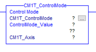
Parameters
Operand | Type | Format | Description |
|---|---|---|---|
CM1T_Disable | CM1T_ControlMode | Tag | Instance tag for the AOI |
CM1T_Axis | CM1T_Axis | Tag | Working tag for the CM1-T axis |
ControlMode_Value | DINT | Immediate/Tag | A value that sets the type of control mode required 0 - POSITION |
Execution
Condition | Action |
|---|---|
prescan | N/A - rung-condition-out is set to false |
rung-condition-in is true |
|
rung-condition-in is false | N/A - rung-condition-out is set to false |
CM1T_MoveAbsolute
This AOI will execute an absolute position move.
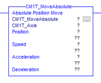
Parameters
Operand | Type | Format | Description |
|---|---|---|---|
CM1T_MoveAbsolute | CM1T_MoveAbsolute | Tag | Instance tag for the AOI |
CM1T_Axis | CM1T_Axis | Tag | Working tag for the CM1-T axis |
Position | DINT | Immediate/ | Target absolute position |
Speed | DINT | Immediate/ | Target speed |
Acceleration | INT | Immediate/ | Target acceleration |
Deceleration (optional) | INT | Immediate/ | Target deceleration |
Execution
Condition | Action |
|---|---|
prescan | N/A - rung-condition-out is set to false |
rung-condition-in is true |
|
rung-condition-in is false | N/A - rung-condition-out is set to false |
CM1T_MoveRelative
This AOI will execute a relative position move.
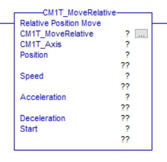
Parameters
Operand | Type | Format | Description |
|---|---|---|---|
CM1T_MoveRelative | CM1T_MoveRelative | Tag | Instance tag for the AOI |
CM1T_Axis | CM1T_Axis | Tag | Working tag for the CM1-T axis |
Position | DINT | Immediate/ | Target absolute position |
Speed | DINT | Immediate/ | Target speed |
Acceleration | INT | Immediate/ | Target acceleration |
Deceleration (optional) | INT | Immediate/ | Target deceleration |
Start | BOOL | Immediate/ | 0 → 1 transition will execute a new relative move. If a motion is currently in process it will increment relative to the current position |
Execution
Condition | Action |
|---|---|
prescan | N/A - rung-condition-out is set to false |
rung-condition-in is true |
|
rung-condition-in is false | N/A - rung-condition-out is set to false |
CM1T_MoveSpeed
This AOI will execute a speed move.
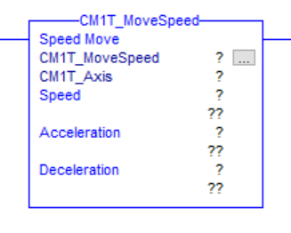
Parameters
Operand | Type | Format | Description |
|---|---|---|---|
CM1T_MoveSpeed | CM1T_MoveSpeed | Tag | Instance tag for the AOI |
CM1T_Axis | CM1T_Axis | Tag | Working tag for the CM1-T axis |
Speed | DINT | Immediate/ | Target speed |
Acceleration | INT | Immediate/ | Target acceleration |
Deceleration (optional) | INT | Immediate/ | Target deceleration |
Execution
Condition | Action |
|---|---|
prescan | N/A - rung-condition-out is set to false |
rung-condition-in is true |
|
rung-condition-in is false | N/A - rung-condition-out is set to false |
CM1T_MoveTorque
This AOI will execute a torque move.
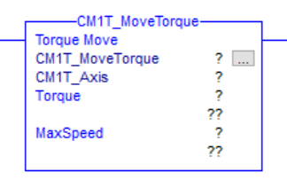
Parameters
Operand | Type | Format | Description |
|---|---|---|---|
CM1T_MoveSpeed | CM1T_MoveSpeed | Tag | Instance tag for the AOI |
CM1T_Axis | CM1T_Axis | Tag | Working tag for the CM1-T axis |
Torque | INT | Immediate/ | Target torque |
MaxSpeed | DINT | Immediate/ | Target speed |
Execution
Condition | Action |
|---|---|
prescan | N/A - rung-condition-out is set to false |
rung-condition-in is true |
|
rung-condition-in is false | N/A - rung-condition-out is set to false |
CM1T_ReadRegister
This AOI loads a register address to read. It returns the register value. The value is returned when the ReadRegister (output) address and the ReadValueAddress (input) address are equal.
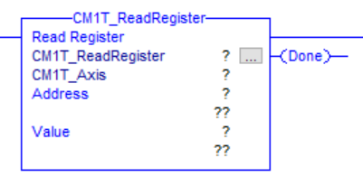
Parameters
Operand | Type | Format | Description |
|---|---|---|---|
CM1T_ReadRegister | CM1T_ReadRegister | Tag | Instance tag for the AOI |
CM1T_Axis | CM1T_Axis | Tag | Working tag for the CM1-T axis |
Address | INT | Immediate/ | Address of register to read |
Value | DINT | Tag | Tag to load the returned value |
Done | BOOL | Tag | Optional output indicating the value has been returned. |
Execution
Condition | Action |
|---|---|
prescan | N/A - rung-condition-out is set to false |
rung-condition-in is true |
|
rung-condition-in is false | N/A - rung-condition-out is set to false |
CM1T_WriteRegister
This AOI loads a register address and value to write. Once the write cycle is complete the done output is set.
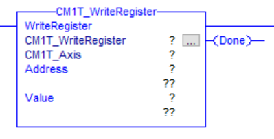
Parameters
Operand | Type | Format | Description |
|---|---|---|---|
CM1TWriteRegister | CM1T_WriteRegister | Tag | Instance tag for the AOI |
CM1T_Axis | CM1T_Axis | Tag | Working tag for the CM1-T axis |
Address | INT | Immediate/ | Address of register to write |
Value | DINT | Immediate/ | Tag/value to load into the write value |
Done | BOOL | Tag | Optional output indicating the value has been written. |
Execution
Condition | Action |
|---|---|
prescan | N/A - rung-condition-out is set to false |
rung-condition-in is true |
|
rung-condition-in is false | N/A - rung-condition-out is set to false |
CML Operation
The following tables outlines the available add-on instructions
Name | Description | Required |
|---|---|---|
CM1T_CMLDataExchange | Exchanges data between the drive and the drive variable | Yes |
CM1T_CMLReadRegister | Reads a motor register | No |
CM1T_CMLWriteRegister | Writes to a motor register | No |
CM1T_CMLDataExchange
This AOI is required if any other CML AOIs are used. One instance is required for each CM1-T axis being controlled.
It has a number of functions
It exchanges data between the motor connections and the motor/drive tag.
It retrieves the drive status and places it into the DriveStatus variable.
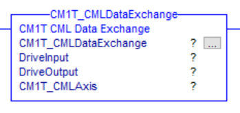
Parameters
Operand | Type | Format | Description |
|---|---|---|---|
CM1T_DataExchange | CM1T_DataExchange | Tag | Instance tag for the AOI |
DriveInput | AB:ETHERNET_MODULE_SINT_32Bytes:I:0 | Tag | Module defined connection input for the CM1-T |
DriveOutput | AB:ETHERNET_MODULE_SINT_20Bytes:O:0 | Tag | Module defined connection output for the CM1-T |
CM1T_Axis | CM1T_Axis | Tag | Working tag for the CM1-T axis |
Execution
Condition | Action |
|---|---|
Prescan | N/A - rung-condition-out is set to false |
Rung Condition - TRUE |
|
Rung Condition - FALSE | N/A - rung-condition-out is set to false |
CM1T_CMLReadRegister
This AOI loads a register address to read. It returns the register value. The value is returned when the ReadRegister (output) address and the ReadValueAddress (input) address are equal.

Parameters
Operand | Type | Format | Description |
|---|---|---|---|
CM1T_ReadRegister | CM1T_ReadRegister | Tag | Instance tag for the AOI |
CM1T_Axis | CM1T_Axis | Tag | Working tag for the CM1-T axis |
Slot | SINT | Immediate/ | There are 5 slots available. Enter 1-5. |
Address | INT | Immediate/ | Address of register to read |
Value | DINT | Tag | Tag to load the returned value |
Done | BOOL | Tag | Optional output indicating the value has been returned. |
Execution
Condition | Action |
|---|---|
prescan | N/A - rung-condition-out is set to false |
rung-condition-in is true |
|
rung-condition-in is false | N/A - rung-condition-out is set to false |
CM1T_CMLWriteRegister
This AOI loads a register address and value to write. Once the write cycle is complete the done output is set.
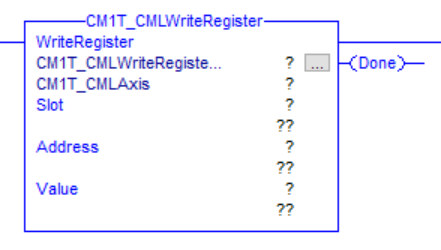
Parameters
Operand | Type | Format | Description |
|---|---|---|---|
CM1TWriteRegister | CM1T_WriteRegister | Tag | Instance tag for the AOI |
CM1T_Axis | CM1T_Axis | Tag | Working tag for the CM1-T axis |
Slot | SINT | Immediate/ | There are 5 slots available. Enter 1-5. |
Address | INT | Immediate/ | Address of register to write |
Value | DINT | Immediate/ | Tag/value to load into the write value |
Done | BOOL | Tag | Optional output indicating the value has been written. |
Execution
Condition | Action |
|---|---|
prescan | N/A - rung-condition-out is set to false |
rung-condition-in is true |
|
rung-condition-in is false | N/A - rung-condition-out is set to false |
Adding CM1-T and AOIs to Project
Download and extract the EtherNet/IP support file.
The file includes the following
Direct Control Operation
CM1T_SampleApplication.ACD - This a sample application built RSLogix. It shows how to
Run the motors in each of the modes
Reset from faults
Enable/Disable the motor
User Data Types (UDT)
Add-On Instructions (AOI)
CML Operation
CM1T_CMLSampleApplication.ACD - RSLogix application to read/write motor registers
CM1T_CMLSampleApplication.crp - Control Room project with CML sample program.
Executes incremental move if variable is set (Run, distance, speed and acceleration set from PLC)
Increments counter variable (Variable read in PLC)
User Data Types (UDT)
Add-On Instructions (AOI)
Direct Control Operation
Import User Data Types (UDTs)
The following steps show how to import the UDTs used by the CM1-T module.
Right click on Data Types → User-Defined and select "Import Data Type..."
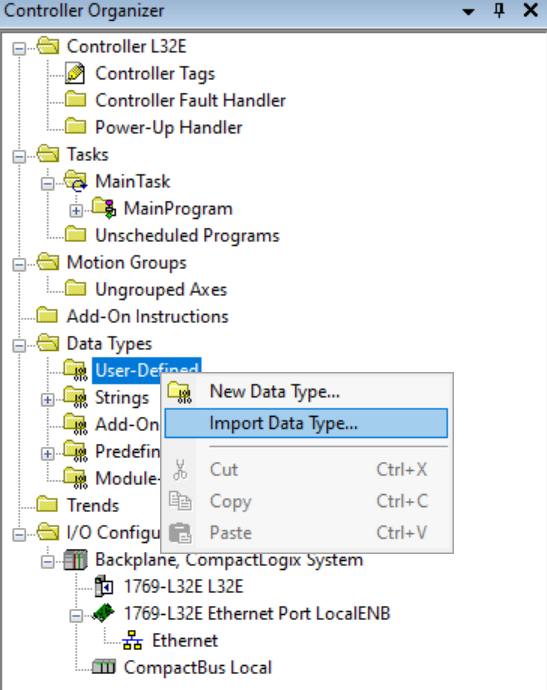
Browse to the location where the CM1T_AOI support file was extracted. Select the CM1T_Axis and click import.

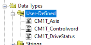
On the Import Configuration window click OK
The CM1T_Axis, CM1T_Controlword and CM1T_DriveStatus should all have been import as shown below. If they were not repeat steps 1-3 with the CM1T_Controlword and CM1T_DriveStatus.
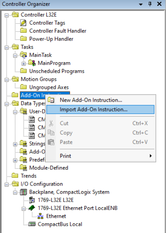
Import Add-On Instructions (AOIs)
The following steps show how to import the CM1-T modules AOIs. The only required AOI is CM1T_DataExchange. All the other AOIs depend on this one to populate the data type.
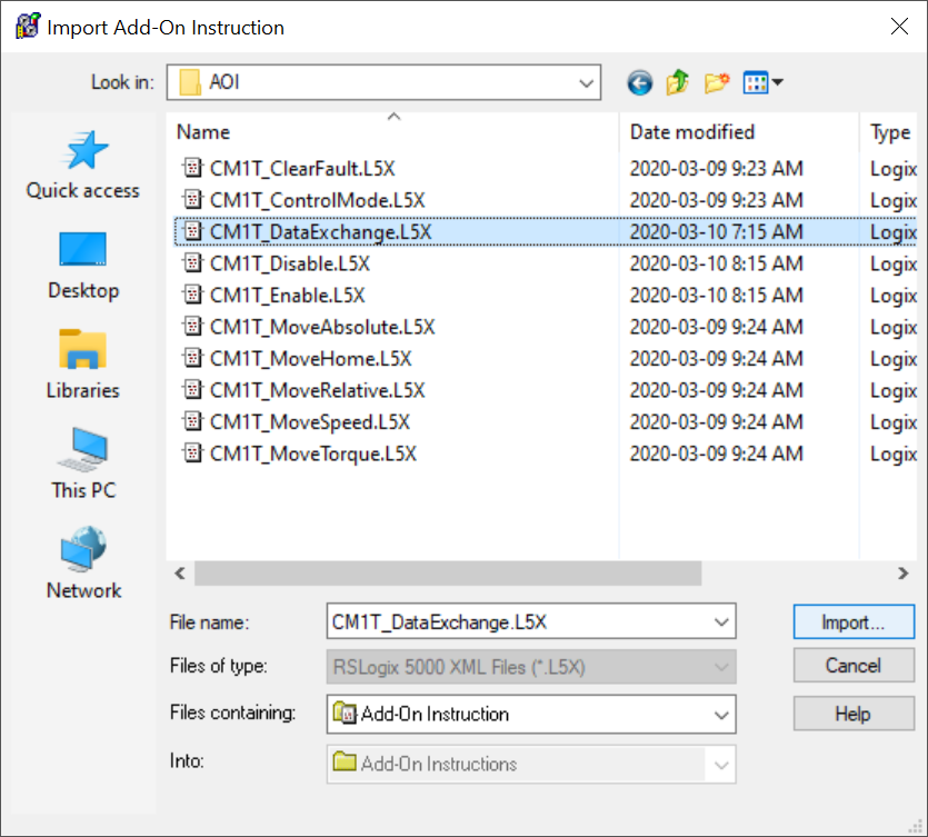
Right click on Add-On Instructions and select "Import Add-On Instruction..."
Browse to the extracted AOI folder and select CM1T_DataExchange. Click Import
On the Configuration Import window click OK.
Repeat steps 1-3 until all required AOIs are imported
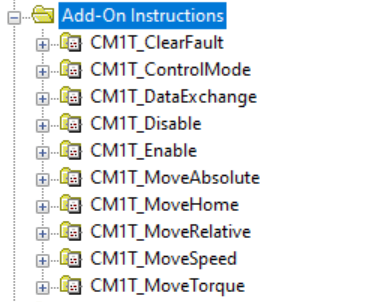
The Add-On Instruction tree will look as follows once all AOIs are imported
Add CM1-T Module
The following steps show how to add an CM1-T module in RSLogix. At present the EtheNet/IP is in testing and the CM1-T is added a a generic module.
Open an existing project or start a new one
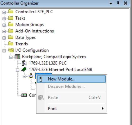
In the Controller Organizer expand I/O Configuration and right click on "Ethernet". Select "New Module"
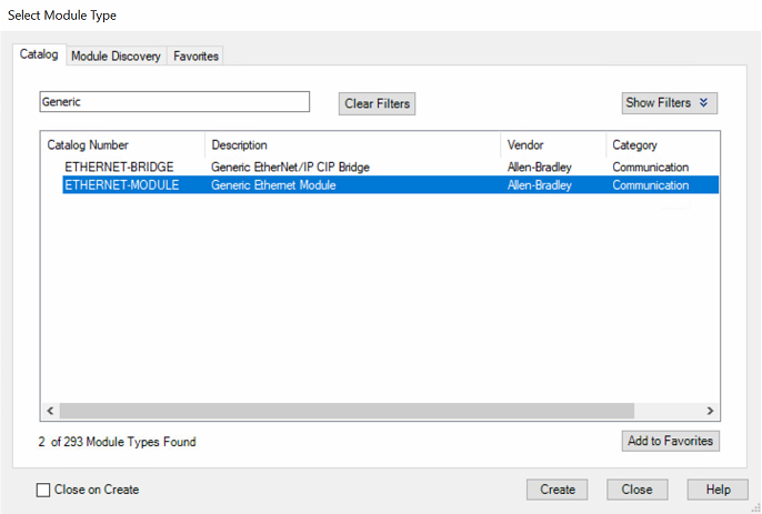
Search "Generic", Select "ETHERNET-MODULE" and click Create
Fill in the following properties shown below
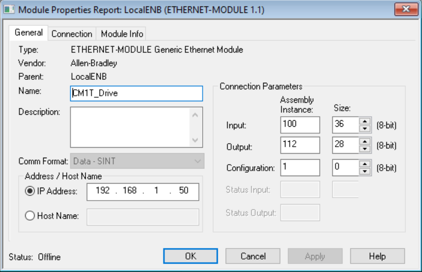
Name: Give the drive a name. E.g. CM1T_Drive, Axis1, LabelXAxis, etc
Comm Format: Data - SINT
IP Address: Enter the IP Address of the CM1-T you are adding.
Connection Parameters
Input: Assembly Instance = 100, Size = 36
Output: Assembly Instance = 112, Size = 28
Configuration: Assembly Instance = 1, Size = 0
Click OK
The Module Properties window should open. If it does not double click on the newly created module inside the Ethernet heading.
Select the Connection Tab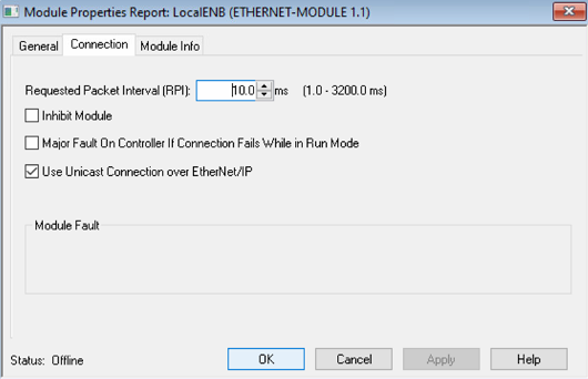
Set the packet interval as required. Typically this would be 10ms.
Check the boxes as shown in the picture above
The final set of steps below shows how to add the CM1T_DataExchange AOI and configure it to exchange data between the tag created for the CM1-T and the CM1-T module. A single instance of the CM1T_DataExchange should be created per module. There should never be more than one per module.
Add the CM1T_DataExchange AOI to a rung
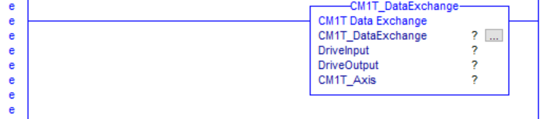
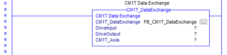
Create a CM1T_DataExchange Tag and attached it to this instance. In this example it is called FB_CM1T_DataExchnage
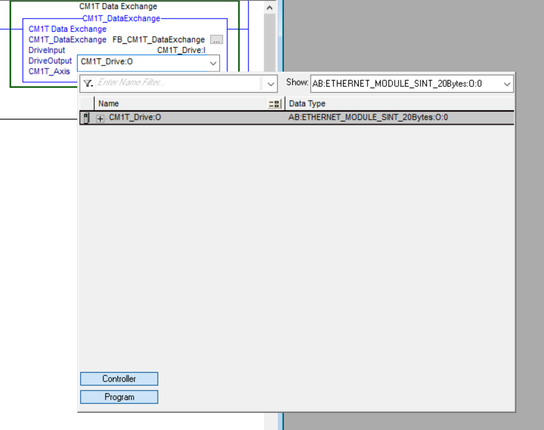
Expand the DriveInput drop down menu and select the CM1T_Drive module input create earlier
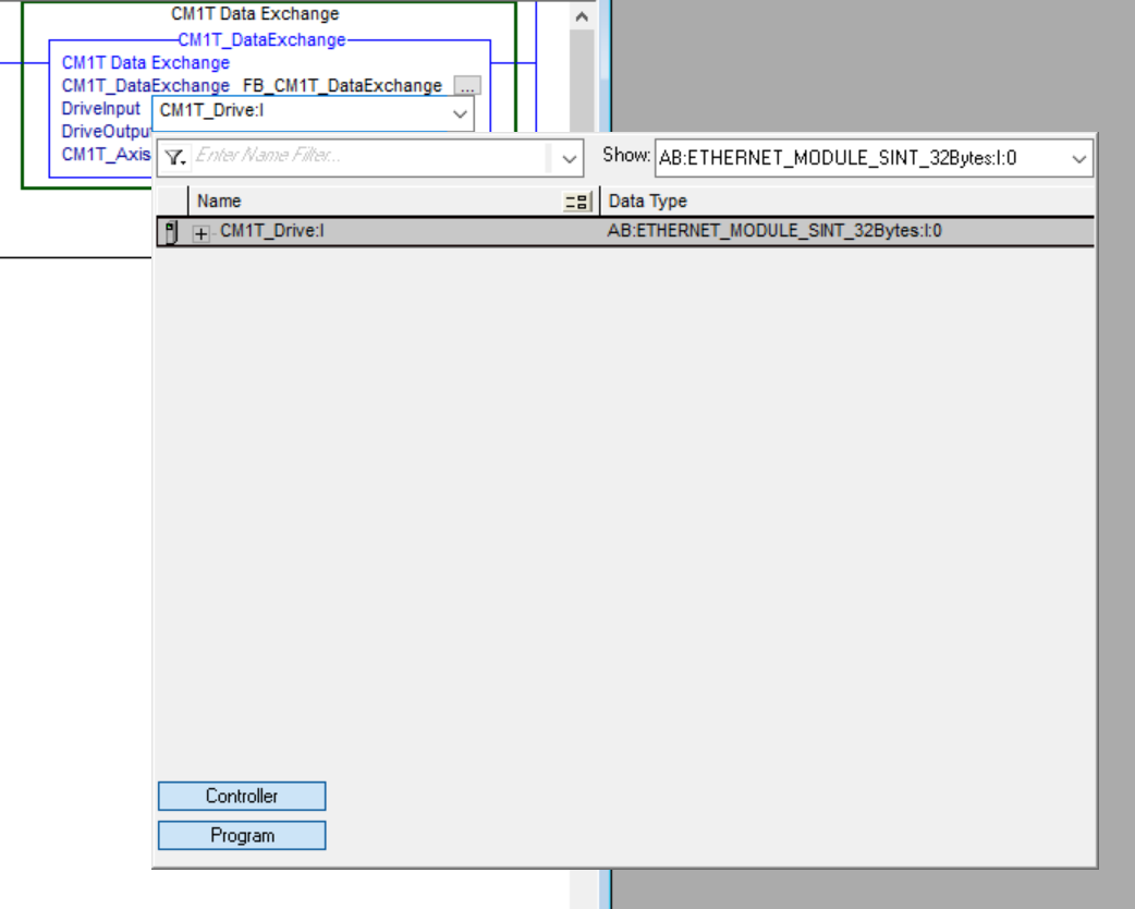
Expand the DriveOuput drop down menu and select the CM1T_Drive module output create earlier
Create a new CM1T_Axis tag and attach it to the instruction. This is the tag that will be used in all other AOIs

All CM1-T AOIs are now ready to be used. See the example application for more details on running the motor.
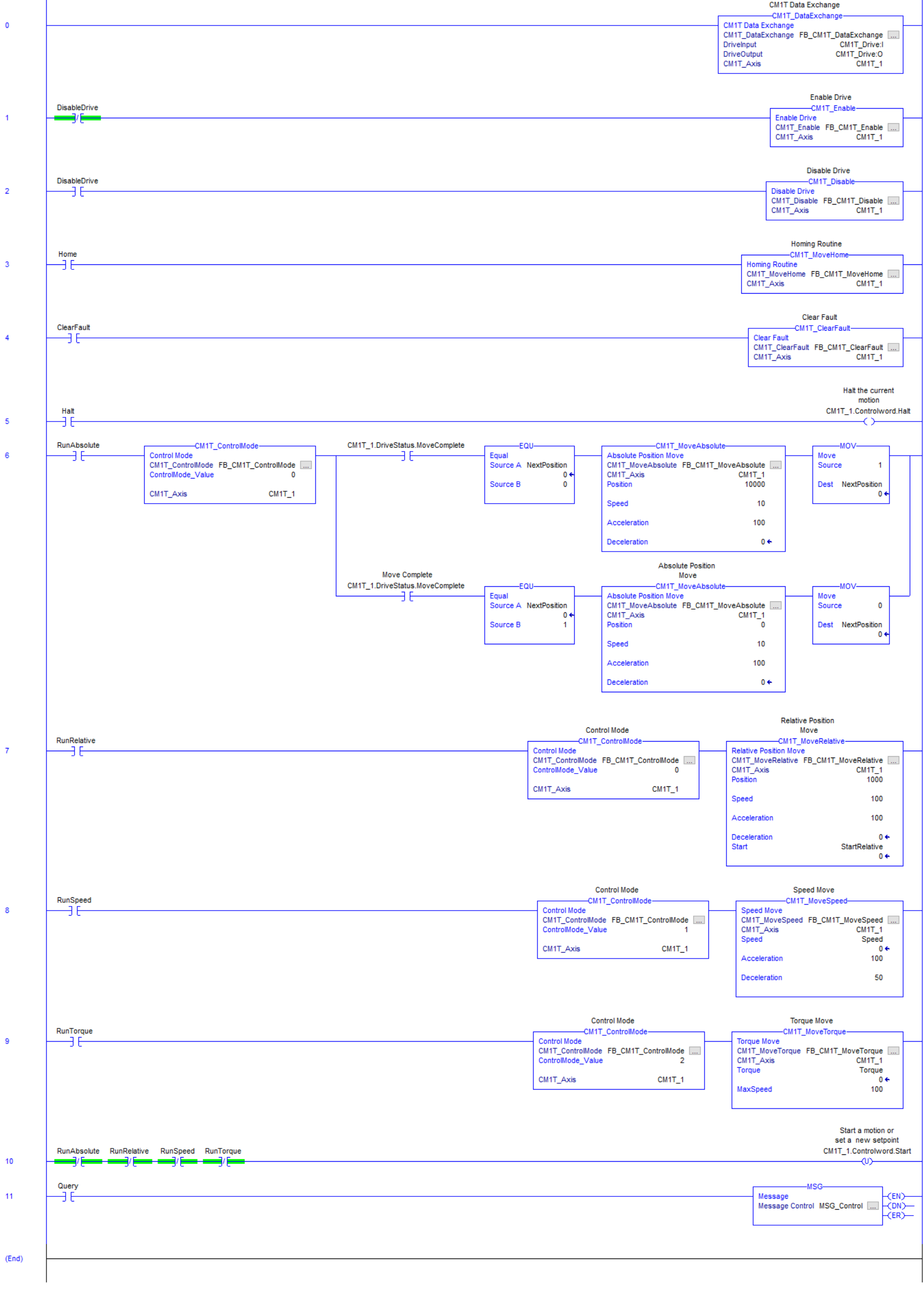
Example Logic - Direct Control Operation Sample
The following logic is from the Direct operation sample application. The example shows how to run the motor in each of the modes, enable, disable, halt, and recover from an error.
CML Operation
Import User Data Types (UDTs)
Following the instructions for Direct Control Operation except import
CM1T_CMLAxis
CM1T_CMLDriveStatus
Import Add-On Instructions (AOIs)
Follow the instructions for Direct Control Operation except import
CM1T_CMLDataExchange
CM1T_CMLReadRegister
CM1T_CMLWriteRegister
Add CM1-T Module
Follow the instructions for Direct Control Operation except on step 4 enter the following configuration data
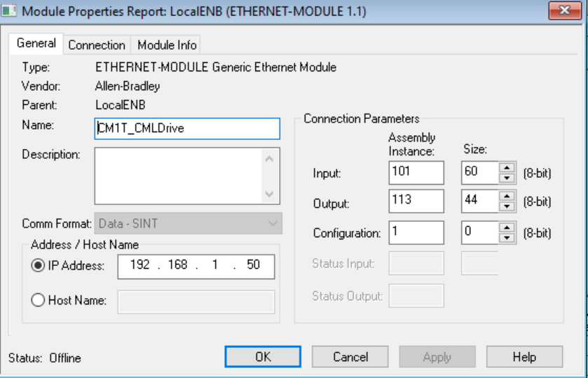
Name: Give the drive a name. E.g. CM1T_Drive, Axis1, LabelXAxis, etc
Comm Format: Data - SINT
IP Address: Enter the IP Address of the CM1-T you are adding.
Connection Parameters
Input: Assembly Instance = 101, Size = 60
Output: Assembly Instance = 113, Size = 44
Configuration: Assembly Instance = 1, Size = 0
Click OK
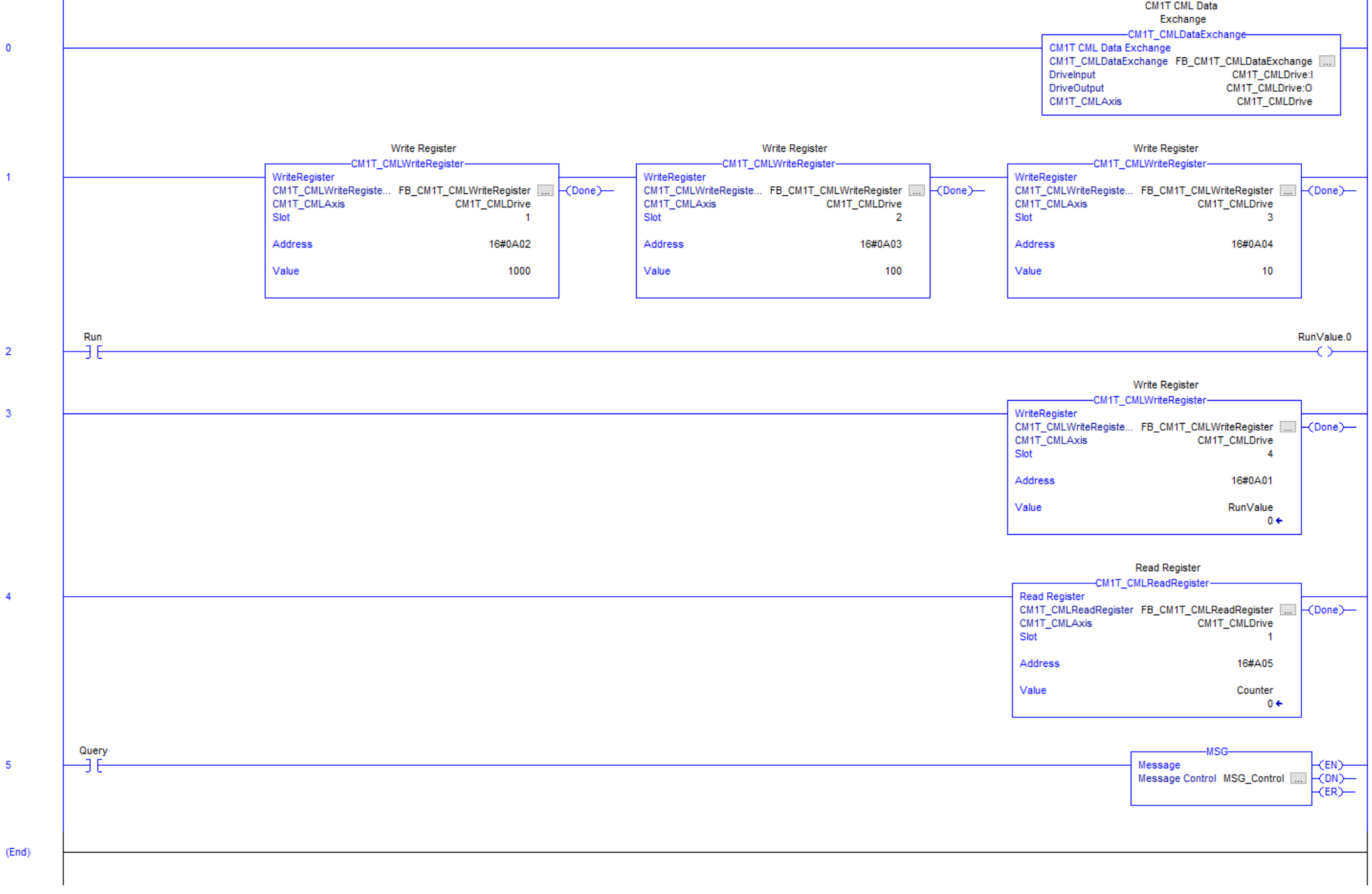
Example Logic - CML Operation Sample
The following sample logic is supplied with the AOIs. It requires the motor to be programmed with a CML program. The program does the following
Motor indexes continuously by the distance amount defined by PLC
Motor indexes with speed and acceleration defined by PLC
Indexing is started and stopped by PLC
A counter showing number of indexes is read by the PLC
Appendix
A - Support Files
B - Complete Register Address Map
K Registers
Register | Address | |
|---|---|---|
Hex | Decimal | |
K21 | 16#0115 | 277 |
K22 | 16#0116 | 278 |
K23 | 16#0117 | 279 |
K24 | 16#0118 | 280 |
K25 | 16#0119 | 281 |
K26 | 16#011A | 282 |
K27 | 16#011B | 283 |
K28 | 16#011C | 284 |
K29 | 16#011D | 285 |
K30 | 16#011E | 286 |
K31 | 16#011F | 287 |
K32 | 16#0120 | 288 |
K33 | 16#0121 | 289 |
K34 | 16#0122 | 290 |
K35 | 16#0123 | 291 |
K36 | 16#0124 | 292 |
K37 | 16#0125 | 293 |
K38 | 16#0126 | 294 |
K39 | 16#0127 | 295 |
K40 | 16#0128 | 296 |
K41 | 16#0129 | 297 |
K42 | 16#012A | 298 |
K43 | 16#012B | 299 |
K44 | 16#012C | 300 |
K45 | 16#012D | 301 |
K46 | 16#012E | 302 |
Register | Address | |
|---|---|---|
Hex | Decimal | |
K47 | 16#012F | 303 |
K48 | 16#0130 | 304 |
K49 | 16#0131 | 305 |
K50 | 16#0132 | 306 |
K51 | 16#0133 | 307 |
K52 | 16#0134 | 308 |
K53 | 16#0135 | 309 |
K54 | 16#0136 | 310 |
K55 | 16#0137 | 311 |
K56 | 16#0138 | 312 |
K57 | 16#0139 | 313 |
K58 | 16#013A | 314 |
K59 | 16#013B | 315 |
K60 | 16#013C | 316 |
K61 | 16#013D | 317 |
K62 | 16#013E | 318 |
K63 | 16#013F | 319 |
K64 | 16#0140 | 320 |
K65 | 16#0141 | 321 |
K66 | 16#0142 | 322 |
K67 | 16#0143 | 323 |
K68 | 16#0144 | 324 |
K69 | 16#0145 | 325 |
K70 | 16#0146 | 326 |
K71 | 16#0147 | 327 |
K72 | 16#0148 | 328 |
Register | Address | |
|---|---|---|
Hex | Decimal | |
K73 | 16#0149 | 329 |
K74 | 16#014A | 330 |
K75 | 16#014B | 331 |
K76 | 16#014C | 332 |
K77 | 16#014D | 333 |
K78 | 16#014E | 334 |
K79 | 16#014F | 335 |
K80 | 16#0150 | 336 |
K81 | 16#0151 | 337 |
K82 | 16#0152 | 338 |
K83 | 16#0153 | 339 |
K84 | 16#0154 | 340 |
K85 | 16#0155 | 341 |
K86 | 16#0156 | 342 |
K87 | 16#0157 | 343 |
K88 | 16#0158 | 344 |
K89 | 16#0159 | 345 |
K90 | 16#015A | 346 |
H Registers
Register | Address | |
|---|---|---|
Hex | Decimal | |
H0 | 16#0200 | 512 |
H1 | 16#0201 | 513 |
H2 | 16#0202 | 514 |
H3 | 16#0203 | 515 |
H4 | 16#0204 | 516 |
H5 | 16#0205 | 517 |
H6 | 16#0206 | 518 |
H7 | 16#0207 | 519 |
P Registers
Register | Address | |
|---|---|---|
Hex | Decimal | |
P0 | 16#0300 | 768 |
P1 | 16#0301 | 769 |
P2 | 16#0302 | 770 |
P3 | 16#0303 | 771 |
P4 | 16#0304 | 772 |
P5 | 16#0305 | 773 |
P6 | 16#0306 | 774 |
P7 | 16#0307 | 775 |
P8 | 16#0308 | 776 |
P9 | 16#0309 | 777 |
P10 | 16#030A | 778 |
P11 | 16#030B | 779 |
P12 | 16#030C | 780 |
P13 | 16#030D | 781 |
P14 | 16#030E | 782 |
P15 | 16#030F | 783 |
P16 | 16#0310 | 784 |
P17 | 16#0311 | 785 |
P18 | 16#0312 | 786 |
P19 | 16#0313 | 787 |
P20 | 16#0314 | 788 |
P21 | 16#0315 | 789 |
P22 | 16#0316 | 790 |
P23 | 16#0317 | 791 |
P24 | 16#0318 | 792 |
P25 | 16#0319 | 793 |
S Registers
Register | Address | |
|---|---|---|
Hex | Decimal | |
S0 | 16#0400 | 1024 |
S1 | 16#0401 | 1025 |
S2 | 16#0402 | 1026 |
S3 | 16#0403 | 1027 |
S4 | 16#0404 | 1028 |
S5 | 16#0405 | 1029 |
S6 | 16#0406 | 1030 |
S7 | 16#0407 | 1031 |
S8 | 16#0408 | 1032 |
S9 | 16#0409 | 1033 |
S10 | 16#040A | 1034 |
S11 | 16#040B | 1035 |
S12 | 16#040C | 1036 |
S13 | 16#040D | 1037 |
S14 | 16#040E | 1038 |
S15 | 16#040F | 1039 |
A Registers
Register | Address | |
|---|---|---|
Hex | Decimal | |
A0 | 16#0500 | 1280 |
A1 | 16#0501 | 1281 |
A2 | 16#0502 | 1282 |
A3 | 16#0503 | 1283 |
A4 | 16#0504 | 1284 |
A5 | 16#0505 | 1285 |
A6 | 16#0506 | 1286 |
A7 | 16#0507 | 1287 |
A8 | 16#0508 | 1288 |
T Registers
Register | Address | |
|---|---|---|
Hex | Decimal | |
T1 | 16#0601 | 1537 |
T2 | 16#0602 | 1538 |
T3 | 16#0603 | 1539 |
T4 | 16#0604 | 1540 |
T5 | 16#0605 | 1541 |
T6 | 16#0606 | 1542 |
T7 | 16#0607 | 1543 |
T8 | 16#0608 | 1544 |
M Registers
Register | Address | |
|---|---|---|
Hex | Decimal | |
M0 | 16#0700 | 1792 |
M1 | 16#0701 | 1793 |
M2 | 16#0702 | 1794 |
M3 | 16#0703 | 1795 |
M4 | 16#0704 | 1796 |
M5 | 16#0705 | 1797 |
M6 | 16#0706 | 1798 |
M7 | 16#0707 | 1799 |
R Registers
Register | Address | |
|---|---|---|
Hex | Decimal | |
R0 | 16#0800 | 2048 |
R1 | 16#0801 | 2049 |
R2 | 16#0802 | 2050 |
R3 | 16#0803 | 2051 |
R4 | 16#0804 | 2052 |
R5 | 16#0805 | 2053 |
R6 | 16#0806 | 2054 |
R7 | 16#0807 | 2055 |
R8 | 16#0808 | 2056 |
R9 | 16#0809 | 2057 |
R10 | 16#080A | 2058 |
R11 | 16#080B | 2059 |
R12 | 16#080C | 2060 |
R13 | 16#080D | 2061 |
R14 | 16#080E | 2062 |
R15 | 16#080F | 2063 |
R16 | 16#0810 | 2064 |
R17 | 16#0811 | 2065 |
R18 | 16#0812 | 2066 |
R19 | 16#0813 | 2067 |
R20 | 16#0814 | 2068 |
R21 | 16#0815 | 2069 |
R22 | 16#0816 | 2070 |
R23 | 16#0817 | 2071 |
R24 | 16#0818 | 2072 |
R25 | 16#0819 | 2073 |
N Registers
Register | Address | |
|---|---|---|
Hex | Decimal | |
N0 | 16#0900 | 2304 |
N1 | 16#0901 | 2305 |
N2 | 16#0902 | 2306 |
N3 | 16#0903 | 2307 |
N4 | 16#0904 | 2308 |
N5 | 16#0905 | 2309 |
N6 | 16#0906 | 2310 |
N7 | 16#0907 | 2311 |
N8 | 16#0908 | 2312 |
N9 | 16#0909 | 2313 |
N10 | 16#090A | 2314 |
N11 | 16#090B | 2315 |
N12 | 16#090C | 2316 |
N13 | 16#090D | 2317 |
N14 | 16#090E | 2318 |
N15 | 16#090F | 2319 |
N16 | 16#0910 | 2320 |
N17 | 16#0911 | 2321 |
N18 | 16#0912 | 2322 |
N19 | 16#0913 | 2323 |
N20 | 16#0914 | 2324 |
N21 | 16#0915 | 2325 |
N22 | 16#0916 | 2326 |
N23 | 16#0917 | 2327 |
N24 | 16#0918 | 2328 |
N25 | 16#0919 | 2329 |
V Registers
Register | Address | |
|---|---|---|
Hex | Decimal | |
V0 | 16#0A00 | 2560 |
V1 | 16#0A01 | 2561 |
V2 | 16#0A02 | 2562 |
V3 | 16#0A03 | 2563 |
V4 | 16#0A04 | 2564 |
V5 | 16#0A05 | 2565 |
V6 | 16#0A06 | 2566 |
V7 | 16#0A07 | 2567 |
V8 | 16#0A08 | 2568 |
V9 | 16#0A09 | 2569 |
V10 | 16#0A0A | 2570 |
V11 | 16#0A0B | 2571 |
V12 | 16#0A0C | 2572 |
V13 | 16#0A0D | 2573 |
V14 | 16#0A0E | 2574 |
V15 | 16#0A0F | 2575 |