
Connectors and LED Information
Overview
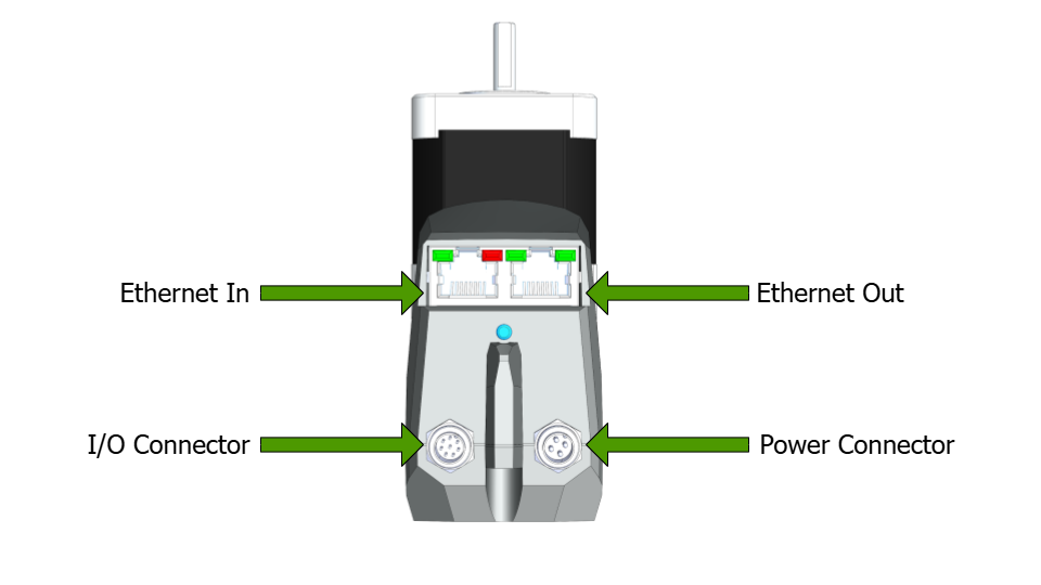
The following diagram shows an overview of all connectors and LEDs.
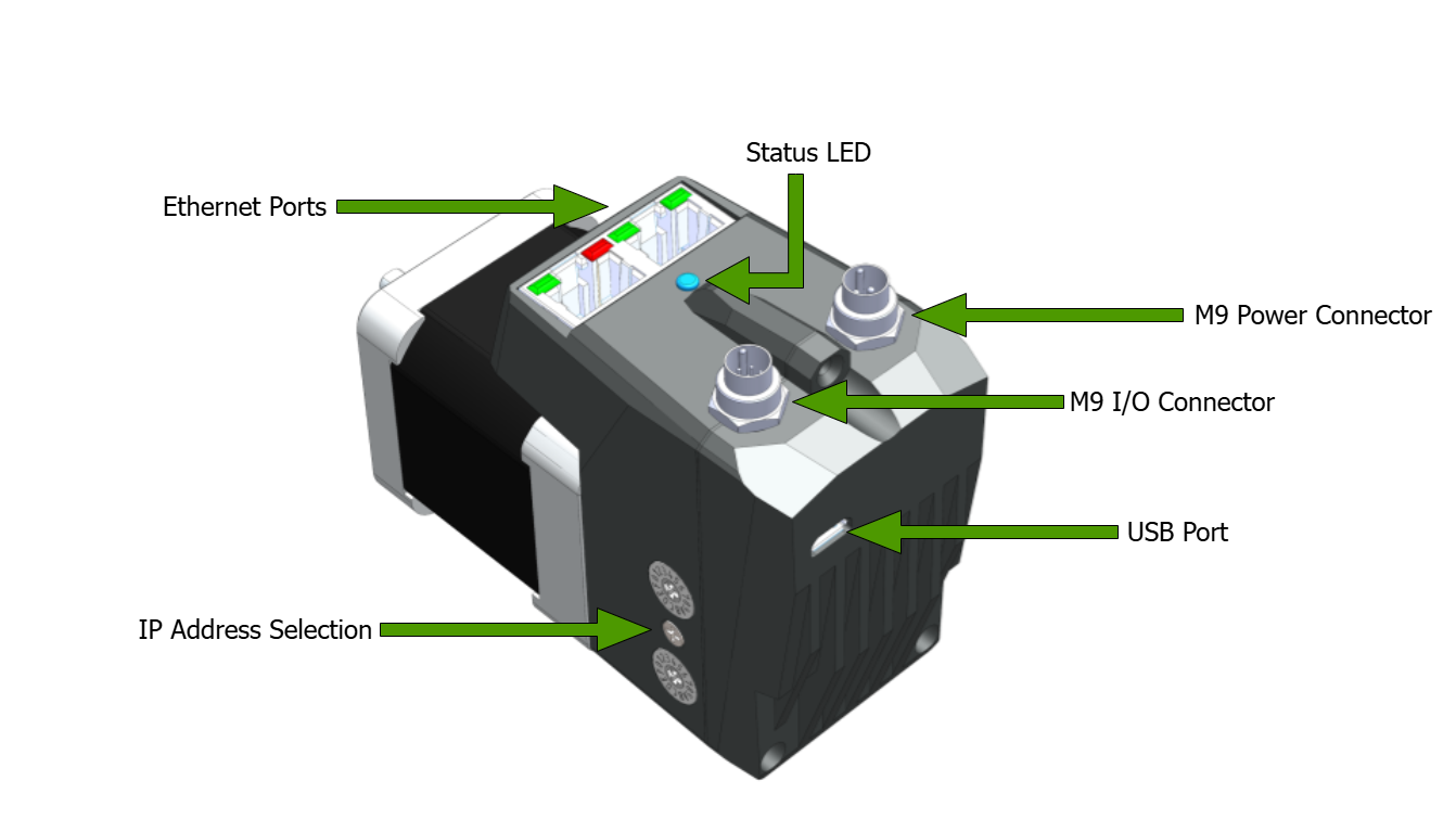
Figure: Overview of Connections and status LEDs
Motor Connections
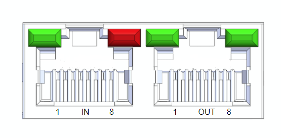
Ethernet Connectors
The Ethernet ports use standard Ethernet RJ45 CAT5e, M8-A or M8-D connectors depending on the motor variant. They are labeled IN and OUT but either port may be used. The CM1-T Ethernet connections will act as a TCP/IP switch. Multiple motors or other devices can be connected in a daisy chain configuration without the need to run back to a central switch for each ethernet device.
Connector Options
RJ45
Amphenol - RJHSE538B02
M8-A Female
TE Connectivity - T4041017041-000
M8-D Female
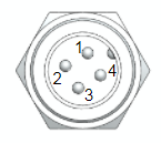
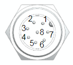
Pinout
RJ45(1) | M8-A | M8-D | |
|---|---|---|---|
Tx+ | 1 | 1 | 1 |
Rx+ | 3 | 2 | 2 |
Rx- | 6 | 3 | 4 |
Tx- | 2 | 4 | 3 |
(1) Pins 4,5,7 and 8 are connected to GND.
Example Cables
All ethernet cables are standard pinouts and are available from a variety of online suppliers or cable houses. Here are a few example cables from the Phoenix Contact NBC series
Image | Part Number | Description | Digikey Link |
|---|---|---|---|
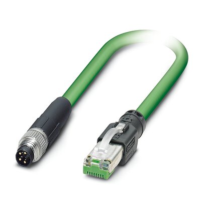 | 1407353 | M8-A male to RJ45 | |
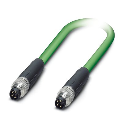 | 1407349 | M8-A male to M8A male | |
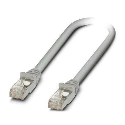 | 1227562 | RJ45 to RJ45 |
Power Connector
The power connector supplies 24V to the TCP/IP slave and the motor separately. These two can be tied together so both are off the same power supply.
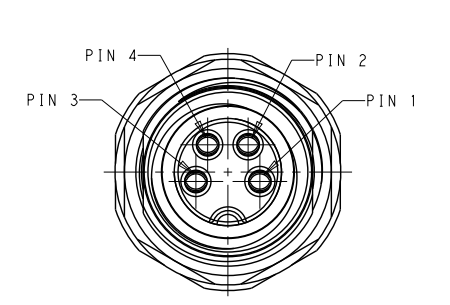
The power connector is an M9 circular connector from Binder. The relevant parts numbers are
Connector | Part Number | Supplier |
|---|---|---|
Motor connector | 09 0081 20 04 | Binder |
Female cable side mating connector | 99 0080 102 04 | Binder |
4m power cable | CM1M9-4F-4000 | Myostat |
The CM1M9-4F-4000 is 24AWG with conductor resistance of 97.5Ω/km
The HF version with EXT-3D cable has a resistance of 91.1Ω/km
Pin # | Description | Voltage | Current |
|---|---|---|---|
1 - yellow | Motor Control Power | 24V ±10% | 125mA max |
2 - white | 0V | - | |
3 - grey | 0V | - | |
4 - orange | Motor Drive Power | 24V ±10% | See individual motor ratings |
Colors indicated are for the standard CM1M9-4F-4000 power cable.
There is no reverse polarity protection. Ensure the 24V power is connected correctly before powering the unit.
Maintaining Control power and switching off motor drive power will
retain motor position
remove any ability for the motor to be driven (as power to the motor drive has been removed).
I/O Connector
Connecting a digital input to GND will produce a logical high on the device.
Connector | Part Number | Supplier |
|---|---|---|
Motor connector | 09 0481 22 08 | Binder |
Female cable side mating connector | 99 0480 102 08 | Binder |
4m I/O cable | CM1M9-8F-4000 | Myostat |
Custom length I/O Cable | CM1M9-8F-xxxxS
| Myostat |
Pin Functions
Pin # | Name | Function | Specifications | |||
|---|---|---|---|---|---|---|
Digital Inputs - Sourcing (supply 0V to trigger) | Parameter | Min | Max | Unit | ||
1 - orange 2 - brown 3 - green 4 - yellow | IN1 IN2 IN3 IN4 | Digital input 1 Digital input 2 Digital input 3 Digital input 4 | Voltage Range | 0 | 36 | V |
Input ON level | 0 | 1.4 | V | |||
Input OFF level | 1.4 | 36 | V | |||
Continuous Current | - | 30 | mA | |||
Peak Current | - | 0.5 | A | |||
Pulse Width | - | 1 | ms | |||
Analog Input (0-5V) | Parameter | Min | Max | Unit | ||
5 - purple | A-IN5 | Analog Input | Voltage Range | 0 | 5 | V |
Resolution | 10 bit | |||||
Digital Outputs - Sinking (output supplies 0V when asserted) | Parameter | Min | Max | Unit | ||
6 - blue 7 - black | OUT1 OUT2 | Digital Output 1 Digital Output 2 | Voltage Range | 0 | - | V |
Continuous Current | - | 1 | A | |||
Inductive Load Peak Rev Current | - | 0.2 | A | |||
Inductive Load Peak Rev Voltage | - | 70 | V | |||
Signal Ground (0V) | Parameter | Min | Max | Unit | ||
8 - red | 0V | 0V | Voltage Range | 0 | 0 | V |
Colors indicated are for the standard CM1M9-8F-4000 I/O cable.
For custom cable length pin-out and colors see CM1M9-8F-xxxxS.PDF
CM1M9-8F-4000 Specifications
Specification | Value |
|---|---|
Length | 4.0m |
Wire Gauge | 26 AWG |
Colour Code | 1 - orange 2 - brown 3 - green 4 - yellow 5 - purple 6 - blue 7 - black 8 - red |
CM1M9-8F-xxxxS Specifications
Specification | Value |
|---|---|
Length | Defined by value in xxxx in millimeters (mm) |
Wire Gauge | 24 AWG |
Colour Code | 1 - orange/Black 2 - orange 3 - Grey/Black 4 - Grey/Red 5 - White/Black 6 - White/Red 7 - Yellow 8 - Yellow/Red |
Drawing |
USB Connection
The USB connector is a standard micro USB and is used to update firmware. When it is plugged into a computer it will create a virtual serial port.
LEDs
Link and Activity LEDs
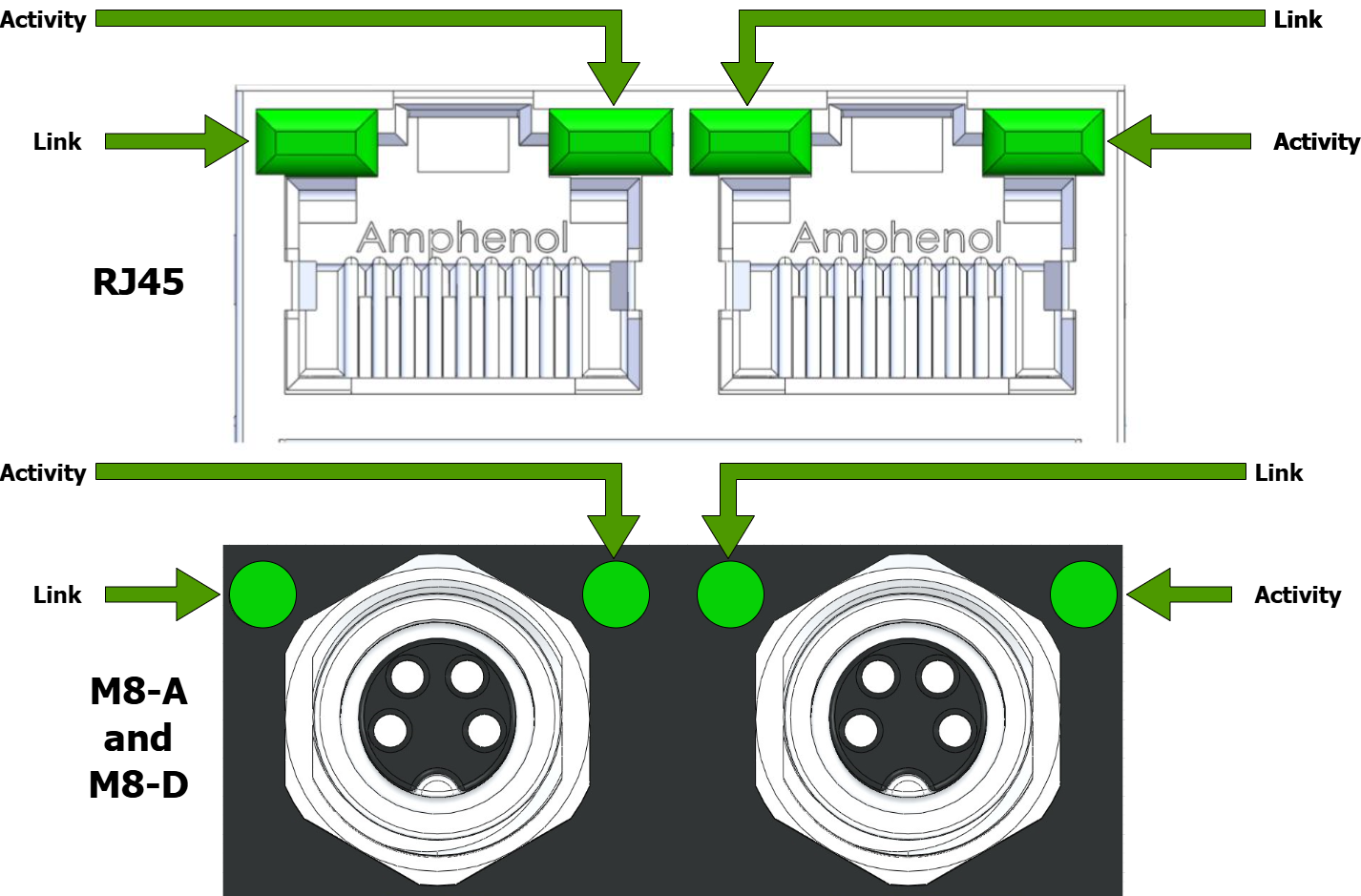
The Link LED will be lit as long as there is a network connection. The activity LED will blink when there is data transfer to/from the motor.
System and Motor Status LED
The system status LED provides feedback to the user on overall system status. The following states exist
GREEN | State | Resolution |
|---|---|---|
Solid | No Error | N/A |
Blinking | No IP Address given |
|
YELLOW | State | Resolution |
Solid | Motor in disabled state (no torque) | Enable motor |
RED | State | Resolution |
Solid | 24V motor drive power not present | Apply 24V drive power |
Blinking | Module error | Unrecoverable - cycle power |
Flashing | 1 - Position error | Clear error/fault |
IP Address Selector
The IP address selector switches will only be active if not using DHCP. If a static IP is programmed with the final value as 0, the rotary selectors will choose the final octet of the IP address.
For example:
Static IP | x10 Value | x1 Value | IP Address used |
|---|---|---|---|
192.168.1.10 | 2 | 3 | 192.168.1.10 |
192.168.1.10 | 0 | 0 | 192.168.1.10 |
192.168.1.0 | 2 | 3 | 192.168.1.35 |
192.168.1.0 | A | 5 | 192.168.1.165 |
192.168.1.0 | E | 3 | 192.168.1.227 |
