
Wiring and LED Information
Overview
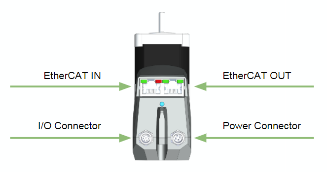
The following diagram shows an overview of all connectors and LEDs.
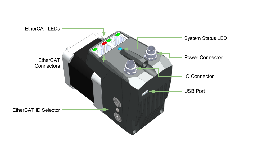
Figure: Overview of Connections and status LEDs
Motor Connections
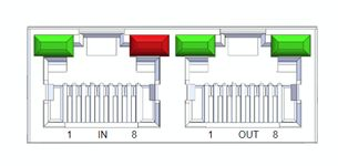
EtherCAT Connectors
The EtherCAT ports use standard Ethernet RJ45 CAT5e, M8-A or M8-D connectors depending on the motor variant. They are labeled IN and OUT as per the EtherCAT standard.
Connector Options
RJ45
Amphenol - RJHSE538B0
M8-A Female
TE Connectivity - T4041017041-000
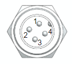
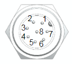
Pinout
RJ45(1) | M8-A | |
|---|---|---|
Tx+ | 1 | 1 |
Rx+ | 3 | 2 |
Rx- | 6 | 3 |
Tx- | 2 | 4 |
(1) Pins 4,5,7 and 8 are connected to GND.
Example Cables
All ethernet cables are standard pinouts and are available from a variety of online suppliers or cable houses. Here are a few example cables from the Phoenix Contact NBC series
Image | Part Number | Description | Digikey Link |
|---|---|---|---|
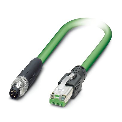 | 1407353 | M8-A male to RJ45 | |
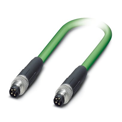 | 1407349 | M8-A male to M8A male | |
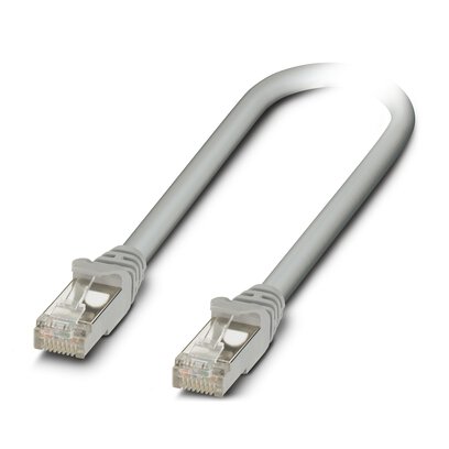 | 1227562 | RJ45 to RJ45 |
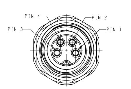
Power Connector
The power connector supplies 24V to the EtherCAT slave and the motor separately. These two can be tied together so both are off the same power supply.
The power connector is an M9 circular connector from Binder. The relevant parts numbers are
Connector | Part Number | Supplier |
|---|---|---|
Motor connector | 09 0081 20 04 | Binder |
Female cable side mating connector | 99 0080 102 04 | Binder |
4m power cable | CM1M9-4F-4000 | Myostat |
The CM1M9-4F-4000 is 24AWG with conductor resistance of 97.5Ω/km
The HF version with EXT-3D cable has a resistance of 91.1Ω/km
Pin # | Description | Voltage | Current |
|---|---|---|---|
1 - yellow | EtherCAT + Motor Control Power | 24V ±10% | 125mA max |
2 - white | 0V | - | |
3 - grey | 0V | - | |
4 - orange | Motor Drive Power | 24V ±10% | See individual motor ratings |
Colors indicated are for the standard CM1M9-4F-4000 power cable.
NOTE: There is no reverse polarity protection. Ensure the 24V power is connected correctly before powering the unit.
Maintaining EtherCAT power and switching off motor drive power will
retain motor position
remove any ability for the motor to be driven (as power to the motor drive has been removed).
I/O Connector
Connecting a digital input to GND will produce a logical high on the device.
All digital inputs can be monitored by the EtherCAT master.
Inputs 2 and 3 are also connected to the motor controller. This allows them to function as inputs for embedded home routines as well as any standard CML programming when in CML mode
The analog input is referenced by the motor and available in CML mode
Output 1 is controller by the EtherCAT slave controller. It is switched on and off by the EtherCAT master
Output 2 can be programmed as a standard motor output and cannot be controller directly by the EtherCAT master.
Connector | Part Number | Supplier |
|---|---|---|
Motor connector | 09 0481 22 08 | Binder |
Female cable side mating connector | 99 0480 102 08 | Binder |
4m I/O cable | CM1M9-8F-4000 | Myostat |
Pin # | Name | EtherCAT Function | Motor Function | Specifications | |||
|---|---|---|---|---|---|---|---|
Digital Inputs - Sourcing (supply 0V to trigger) | Parameter | Min | Max | Unit | |||
1 - orange 2 - brown 3 - green 4 - yellow | IN1 IN2 IN3 IN4 | Digital input 1 Digital input 2 Digital input 3 Digital input 4 | - Digital input 2 Digital input 3 - | Voltage Range | 0 | 36 | V |
Input ON level | 0 | 1.4 | V | ||||
Input OFF level | 1.4 | 36 | V | ||||
Continuous Current | - | 30 | mA | ||||
Peak Current | - | 0.5 | A | ||||
Pulse Width | - | 1 | ms | ||||
Analog Input (0-5V) | Parameter | Min | Max | Unit | |||
5 - purple | A-IN5 | - | Analog input 4 | Voltage Range | 0 | 5 | V |
Resolution | 10 bit | ||||||
Digital Outputs - Sinking (output supplies 0V when asserted) | Parameter | Min | Max | Unit | |||
6 - blue 7 - black | OUT1 OUT2 | Digital output 1 - | - Output 2 | Voltage Range | 0 | - | V |
Continuous Current | - | 1 | A | ||||
Inductive Load Peak Rev Current | - | 0.2 | A | ||||
Inductive Load Peak Rev Voltage | - | 70 | V | ||||
Signal Ground (0V) | Parameter | Min | Max | Unit | |||
8 - red | 0V | 0V | 0V | Voltage Range | 0 | 0 | V |
Colors indicated are for the standard CM1M9-8F-4000 I/O cable.
For custom cable length pin-out and colors see CM1M9-8F.PDF
USB Connection
The USB connector is a standard micro USB and is used to update the EtherCAT firmware. When it is plugged into a computer it will create a virtual serial port.
LEDs
EtherCAT Status LEDs
An EtherCAT slave device is required to have LEDs indicating different states.
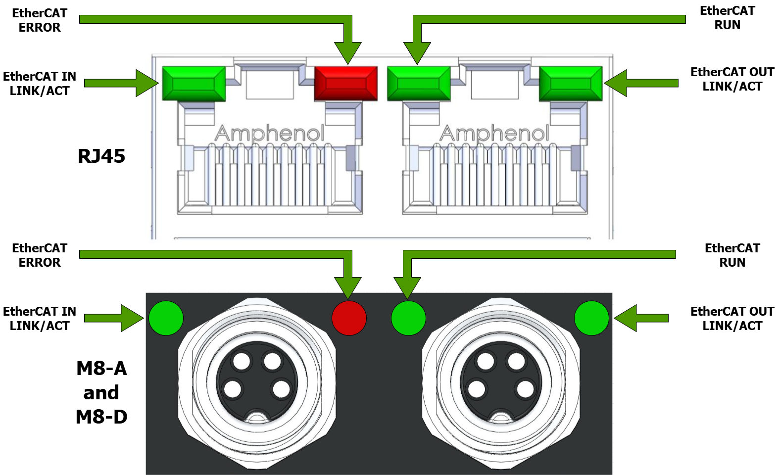
Link/Activity Indicator
There is a Link/Activity LED for both the IN and OUT EtherCAT ports. The table below describes the indicator conditions and their associated states
Link | Activity | Condition | Link/Activity Code |
|---|---|---|---|
Yes | No | Port Open | On |
Yes | Yes | Port Open | Flickering |
No | N/A | Port Closed | Off |
Run Indicator
The Run indicator shows the state of the EtherCAT State Machine. The indicator states are described in the table below.
Indicator State | Slave State | Description |
|---|---|---|
Off | Initialisation | The device is in state "Init" |
Blinking | Pre-Operational | The device is in state "Pre-Operational" |
Single Flash | Safe-Operational | The device is in state "Safe-Operational" |
On | Operational | The device is in state "Operational" |
Flickering | Init or Bootstrap | The device is booting and has not yet entered the "Init" state or, |
Error Indicator
The Error indicator shall show device and EtherCAT errors. Errors are as defined in the table below.
Error State | Error Name | Description | Example |
|---|---|---|---|
On | Application controller | A critial communication or application error has occured |
|
Double flash | Process Data Watchdog timeout/ | An application watchdog timeout has occured | Sync Manager watchdog timeout |
Single flash | Local Error | Slave device application has changed the EtherCAT state autonomously, due to local error. | Device has changed from Op to safe-op due to EtherCAT error |
Blinking | Invalid Configuration | General Configuration error | |
Flickering | Booting Error | Init state reached but boot error detected | Application boot error |
Off | No Error | Device is in working condition |
System and Motor Status LED
The system status LED provides feedback to the user on overall system status. The following states exist
LED Colour | Description |
|---|---|
Red | Motor Error Solid:
Blinking
Flashing:
|
Green | Solid - CiA402 Mode |