Version: 1.0.1
Introduction
The Cool Muscle CM1 can be controlled by the ProCommander 3 from Weigl. Additional information on the capabilities of the ProCommander can be found at http://www.weiglworks.com/products/procom/. This documentation assumes some knowledge of the ProCommander 3 and how to use it.
The ProCommander 3 communicates to a maximum of 8 Cool Muscle motors over UDP. The Cool Muscle is added to the timeline as a 16-bit analog channel which defines the motor's absolute position in time. Figure 1 shows the system architecture including a switch and PC to run the relevant software.
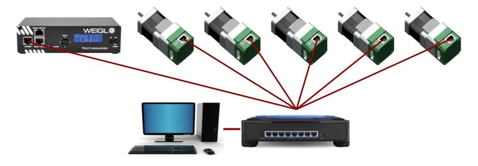 Figure 1: System architecture
Part numbers and accessories
The 17 and 23 series Cool Muscles have an ethernet communication interface integrated onto the motor. The following part numbers will ensure the correct hardware and settings are delivered when a motor is ordered.
Motor part numbers
- 23 Series
- CM1-C-23L20E-WGLA
- CM1-C-23S30E-WGLA
- 17 Series
- CM1-C-17L30E-WGLA
- CM1-C-17S30E-WGLA
Motor Accessories
Additional cable accessories are available. The standard motor includes a 40cm long power cable.
- Power Cables
- CM1IPX1-2000 - standard 2m power cable
- CM1IPX1-XXXX - custom length power cable. Replace XXXX with length in mm.
- IO Cables
- CM1IPX2-2000 - standard 2m IO cable
- CM1IPX2-XXXX - custom length IO cable. Replace XXXX with length in mm
Software
Two software applications are required for setup and show programming
- Contours - download
- Contours is used to setup homing parameters for each axis.
- Support for Contours is through Myostat Motion Control©
- Weigl Hardware Configurator - download
- Configurator is used to setup the ProCommander 3 with the Cool Muscle
- The Weigl Hardware Configurator must be version 1.23 or higher.
- Support for the Hardware Configurator is through Weigl©
Network Setup
The system network must be configured as shown in figure 1. The computer, Cool Muscles and the ProCommander 3 all need to be setup with the same IP range and subnet mask. The following defaults are set
| IP | Subnet | |
|---|---|---|
| Cool Muscle | 10.0.0.201 | 255.255.255.0 |
| Procommander 3 | 10.0.0.101 | 255.255.255.0 |
Changing the Cool Muscle Network IP
All Cool Muscle motors have the same default IP address. If there is more than 1 motor on the system then all additional motors shall require unique IP addresses. Use the following steps to set the IP address.
The motors MUST have sequential addresses. The ProCommander 3 is given the first IP and the number of motors and assumes the addresses are sequential.
- Power up only the Cool Muscle intended to change. If multiple Cool Muscles with the same IP are powered there will be an IP conflict.
- Ensure the computer network is set to the same range as the Cool Muscle.
- IP = 10.0.0.X
- Subnet = 255.255.255.0
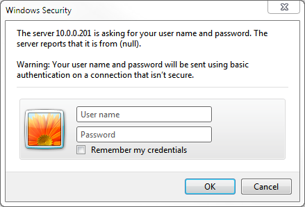
- Using the default browser navigate to http://10.0.0.201
- Leave the admin user name and password blank and click OK
- Select Network on the top left corner
- Enter the desired IP Address
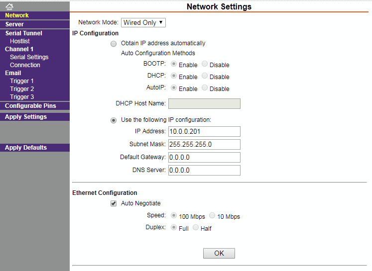
- Click OK at the bottom of the page
- Click Apply Settings on the left colomn
- The unit will now load the new settings and cycle power
Do not change any other settings as this could break communication to the Cool Muscle.
Set up the ProCommander 3
The ProCommander 3 must be setup with information about the Cool Muscles. This sets up how many motors are on the system, their IP addresses and some relevant parameters. Commands are sent through the Hardware Configurator console.
Once all commands have been sent the ProCommander 3 must be power cycled to initialise the motors. The following occurs on a power up
- A connection is established between the ProCommander 3 and the Cool Muscle
- The home routine is started
- Once the home routine is completed all setup parameters are loaded
- Analog channel contolling the motors starts.
By default the home routine is set to run counter clockwise to a hardstop with 30% of the motors torque.
Command List
| Command | Description | Example |
|---|---|---|
| !aipIP:10001:2:MOTORS# | Initialize ProCommender 3 with
| !aip10.0.0.201:10001:2:2# Expected response: >!aip10.0.0.201:10001:2:2# |
| !asxA:val# | Set the position range of the Cool Muscle in 0.01 revolutions.
| !asx1:200# Expected response: >!asx1:200# (this will set the analog range to 2 revolutions) |
| !assA:val# | Set the maximum speed of the Cool Muscle in rpm
| !ass1:100# Expected response: >!ass1:100# (this will set the maximum motor speed to 100 rpm) |
Example:
The following sequence of commands sets up 2 motors starting at IP 10.0.0.201. Motor range is set to 2 revolutions for both motors and the maximum speed is set to 100 rpm.
Commands and their responses can be seen in Figure 2.
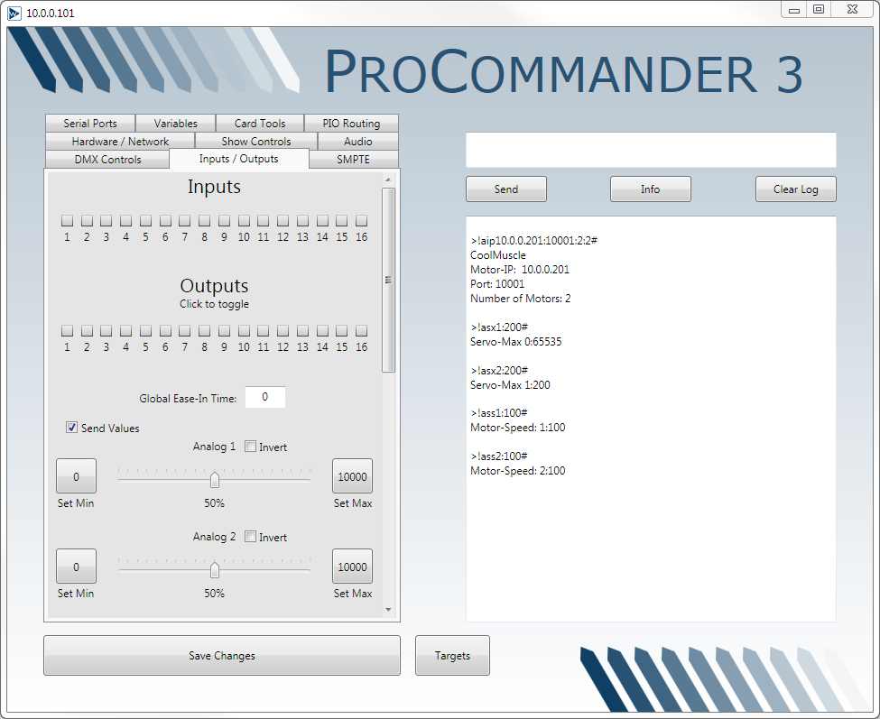
Figure 2: Hardware Configurator setup
Power cycling the ProCommander 3 will initiate the motor initialization. Once the power cycle routine is complete you can test the motors by selecting the Inputs/Outputs tab, checking the Send Values checkbox and sliding the analog sliders.
Setting the Home Routine
Contours is used to set the home routine.
The ProCommander 3 and Contours use the same port to communicate to the motor. The ProCommander 3 should be switched off during this procedure.
Additional Cool Muscle information
- The motor resolution is 50000 counts per revolution.
- Contours by default has a position multiplier of 50000. This means that all units in Contours are in 1 revolution.
A Query button in available in Contours to retrieve the current motors parameters. Figure 3 below shows the Homing Parameters in Contours
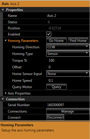
Figure 3: Homing Parameters
The following basic routin should be followed when setting up the home routine
- Switch off the ProCommander 3
- Having both ProCommander 3 and Contours functioning will create conflict in Communication to the motor.
- Cycle power on the motors
- If the ProCommander 3 was initially on then the motors need to be switched out of the mode used by the ProCommander. The easiest way to achieve this is with a power cycle.
- Open Contours
- Add the required axes and connect
- Set the home parameters (the Query button will allow you to see what is currently set)
- Click the find Find Home button to load the parameters and run a home routine.
- When you are happy with the routine close Contours. Save first if you want to retain the setup for later use.
Homing Options
The following homing options are available.
Homing Type
The homing type can be set to
- Hardstop
- Sensor
- Hardstop on power up
- Sensor on power up
A hardstop home routine uses limited torque to run up against an endpoint. Detecting an increase in current it will back off very slightly and set this to the 0 position. It backs up to the previous encoder count to achieve maximum repeatability. If an offset it used it will move the offset and then set the 0 position.
A sensor home routine will run in the direction specified until it detects an input on the input specified. It will then back up to the edge of the sensor for maximum repeatability. If an offset it used it will move the offset and then set the 0 position. If the sensor is active when the home routine is initiated it will initially move in the opposite direction to try and clear the sensor.
It is recommended if possible to use the hardstop home routine. It simplifies wiring and cost and is very repeatable.
The ProCommander 3 issues a homing command on power up. It is recommended to set the home routine to Hardstop or Sensor to not conflict with the ProCommander 3 home command.
Homing direction
The homing direction can be set to Clockwise (CW) or Counter Clockwise (CCW). This is the direction the motor will start homing in.
Torque
The motor torque can be limited during the home search. When the type is set to hardstop it uses the increase above this threshold to detect the hardstop. When the type is set to sensor it limits the motor torque during the routine.
Offset
If the required 0 point is not at the mechanical origin of the machine then an offset can be entered. The motor will move the offset before setting the 0 position. The offset unit is by default motor revolutions. This can be changed in the Axis Properties by changing the Unit Multiplier value.
The following restrictions apply to the offset if the type is set to Hardstop
- If the direction is set to CCW then only a positive offset can be entered
- If the direction is set to CW than only a negative offset can be entered.
The above restrictions do not apply to a sensor home routine.
Home Sensor Input
Select the input that the home sensor is wired too. This only applies to sensor type home routines.
Home Speed
The home speed unit is is by default motor revolutions/second. This can be changed in the Axis Properties by changing the Unit Multiplier value.
Home Routine Example
This example will set the following
Motor 1: CW home routine to a hardstop with 1/2 revolution offset in the negative/CCW direction. It should be run to a torque limit of 45%. Speed is 0.1 rev/s.
Motor 2: CCW home routine to a sensor on IN2 with no offset. It should be run at 60% torque. Speed is 0.25 rev/s.
- Ensure the ProCommander 3 is switched off.
- Cycle power on the motors.
- Open Contours, select the Axes tab on the top left
- Click New twice to add 2 axes (motors)
- Select Axis 1 and Click Manage in the propery grid under the propery Connections.
- You should now have a window open similar to Figure 4.
- The Connections Window shows 2 motors with their serial numbers.
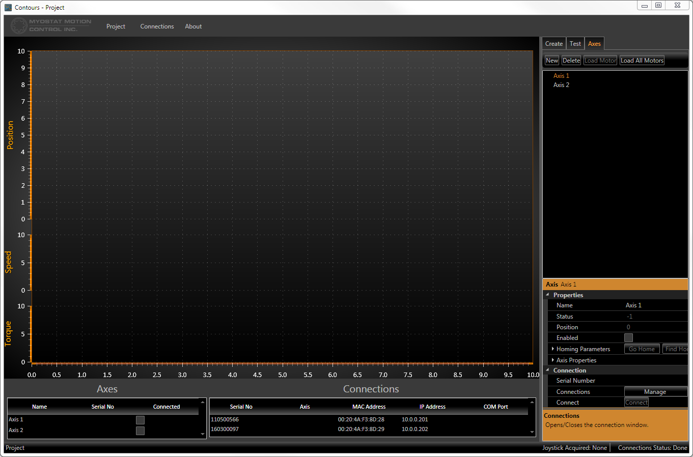
Figure 4: Contours with axes connections - Select a connection in the Connections list and drag and drop onto the desired axis in the Axes list.
- Click the Connected checkbox for each Axis
- The Connections Manager window should look similar to Figure 5.
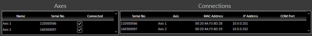
Figure 5: Connections Manager - The Connections Manager window should look similar to Figure 5.
Expand the homing parameters and select the following for Axis 1
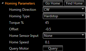
Figure 6: Axis 1 Homing Parameters- Homing Direction: CW
- Homing Type: Hardstop
- Torque: 45
- Offset: -0.5
- Home Sensor Input: None
- Home Speed: 0.1
Click the Find Home button to save and test the home routine
Select Axis 2 and set the following
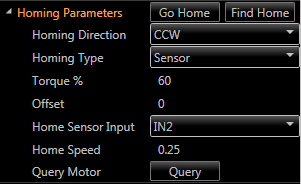
Figure 7: Axis 2 Homing Parameters- Homing Direction: CCW
- Homing Type: Sensor
- Torque: 60
- Offset: 0
- Home Sensor Input: IN2
- Home Speed: 0.25
Click the Find Home button to save and test the home routine
- Save the project if required and close Contours.
Overview
Content Tools