Page History
| Metadata (Metadata Plugin) | ||||
|---|---|---|---|---|
| ||||
1.0.0 |
| Scroll Ignore | ||||
|---|---|---|---|---|
Version:
|
Wiring the CM1
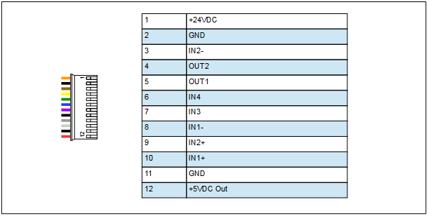
The CM1 motor connects to everything via the 12-pin molex connector on the top of the motor. This connection includes power, communications, and all of the inputs and outputs to the motor.
| Imageplus | ||||||||
|---|---|---|---|---|---|---|---|---|
| ||||||||
|
| Section | |||||||||||||||||||||||||||||||||||||||||||||||||
|---|---|---|---|---|---|---|---|---|---|---|---|---|---|---|---|---|---|---|---|---|---|---|---|---|---|---|---|---|---|---|---|---|---|---|---|---|---|---|---|---|---|---|---|---|---|---|---|---|---|
|
Power
The CM1 motor is powered by the orange and black, pins 1 and 2 on the 12-pin connector. Pin 1, orange, is the positive connector for +24VDC and pin 2, black, is for the ground connection. A green varistor is supplied with the motor. This should be placed across the power terminals to help reduce any spikes or voltage feedback from sudden changes in the speed of the motor. The varistor should be placed as close to the motor as possible.
A five volt output and ground are also provided from the motor on pins 12 and 11 respectively. This can be used to power inputs and outputs, or other devices as required. The five volt output has a maximum current of 50mA.
| Note |
|---|
The power GND connections on the motor are common and are NOT chassis grounds. |
Communications
| Anchor | ||||
|---|---|---|---|---|
|
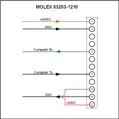
The CM1 motor is capable of natively communicating TTL level serial communications. Other interfaces are available, for further information see CM1 Interface Modules.
Communications are achieved by using input one and output one as serial ports. This means that if you have your CM1 motor connected to a PC or other serial controller you will not be able to use input 1 or output 1 as digital I/O.
See the diagram below for how to connect the CM1 motor for standard TTL serial communications. The Rx and Tx in the diagram refer to the receive and transmit on the user device.
| Imageplus | ||||||||
|---|---|---|---|---|---|---|---|---|
| ||||||||
|
| Note |
|---|
The diagram in Fig.2 shows the connection for an inverted Tx from the computer, as used in the USB Y-Cable. For a non-inverted UART, the Tx should connect to pin 10, and pin 8 should be connected to ground. |
| Anchor | ||||
|---|---|---|---|---|
|
Using a Y-Cable
The USB Y-Cable (CM1US1-1800) is the basic power and communications cable for use with the CM1 motor and your PC. This cable comes pre-wired with a 12-pin connector on one end, and the other end has two connections: a USB plug for connecting to your PC, and a pair of wires for connecting your 24VDC power supply. Upon plugging the USB plug in to your PC, windows should automatically install drivers for this cable. If this does not happen, or there is a problem with the driver installation you may also find these drivers at: http://myostat.ca/CoolMuscleSoftware under “USB Communications Cable Driver”. This cable will emulate a serial COM port on your computer. Once connected, you can communicate to the motor using any standard terminal software, or the Control Room software.
The default baud rate for the motor is 38400, and if you are using a terminal software you will need to set it to 8 data bits, 1 stop bit, no parity.
A serial An RS232 option for the yY-cable is also available with a DE-9 connector (CM1C3-1800). This is particularly useful for connecting the motor directly to PLCs or HMIs requiring serial communication.
Serial Communication Settings
The default baud rate for the motor is 38400.
If you are using a terminal software you will need to set it to:
8 data bits
1 stop bit
no parity
no flow control
Each command to the motor must be terminated with a carriage return.
Networking Multiple CM1 Motors
Up to 15 CM1 motors can be connected in a daisy chain network. While daisy chained, the motors are in communication with each other and you may communicate to all motors through the serial connection.
The CM1 network functions in a master/slave configuration. The first motor on the daisy chain will be designated motor one and this motor will be the master. All communications must pass through this motor.
When multiple motors are connected they are designated with a decimal number, called the motor ID, after all commands. For example, if I want to program a value in P1 for motor one (the master) and motor two, I need to send:
P1.1=100
P1.2=500
P1.1 refers to the P1 register in motor one, and P1.2 refers to the P1 register in motor 2. This is true for any command that you send to the motor.
If a motor ID is not specified, the motors will assume you are communicating to the last motor that was specified. In this way it is possible to send:
P1.1=100
P2=50
P3=500
P1.2=500
P2=1000
The network will understand this as me sending the first three values to motor one, and the last two values to motor two.
| Anchor | ||||
|---|---|---|---|---|
|

Communicating with your CM1 using Control Room
Control Room is the recommended control software for communicating and programming the CoolMuscle motors. This software can be downloaded from: http://myostat.ca/CoolMuscleSoftware under “CM1 and CM2 Interface Software”.
After Running Control Room you will be shown the main window. By default this consists of the Terminal window, the Program window, and the Control window.
Along the top of the screen is the ribbon bar with tabs for various functions. When you first open the program you will be on the “connection” tab. Select the COM port you wish to connect to, as well as the baud rate. By default, the baud rate in the motor is 38400. Once you have selected the correct COM port and baud rate, press the “Connect to Port” button, and you will be connected and ready to communicate to the motor.

For more information on Control Room, see Control Room.
Overview
Content Tools