Page History
...
Ethernet Connectors
The Ethernet IN and OUT ports use standard Ethernet RJ45 CAT5e, M8-A or M8-D connectors depending on the motor variant. They are labeled IN and OUT but either port may be used.
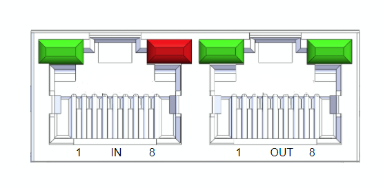
The CM1-T Ethernet connections will act as a TCP/IP switch, allowing multiple . Multiple motors or other devices to can be connected in a daisy chain configuration without the need to run a separate ethernet connection back to a central demarcation for each motor. switch for each ethernet device.
Connector Options
RJ45
- Amphenol - RJHSE538B02
M8-A Female
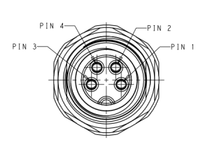
- TE Connectivity - T4041017041-000
- M8-D Female
Pinout
| RJ45(1) | M8-A | M8-D | |
|---|---|---|---|
Tx+ | 1 | 1 | 1 |
| Rx+ | 3 | 2 | 2 |
| Rx- | 6 | 3 | 4 |
| Tx- | 2 | 4 | 3 |
(1) Pins 4,5,7 and 8 are connected to GND.
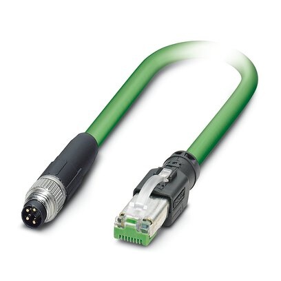
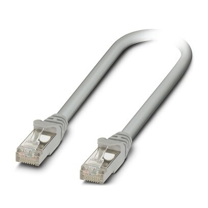
Example Cables
All ethernet cables are standard pinouts and are available from a variety of online suppliers or cable houses. Here are a few example cables from the Phoenix Contact NBC series
| Image | Part Number | Description | Digikey Link |
|---|---|---|---|
| 1407353 | M8-A male to RJ45 | Digikey - 1407353 |
| 1407349 | M8-A male to M8A male | Digikey - 1407349 |
| 1227562 | RJ45 to RJ45 | Digikey - 1227562 |

Power Connector
The power connector supplies 24V to the TCP/IP slave and the motor separately. These two can be tied together so both are off the same power supply.
...
| Section | ||||||||||||||||||||||
|---|---|---|---|---|---|---|---|---|---|---|---|---|---|---|---|---|---|---|---|---|---|---|
|
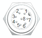
Pin Functions
| Pin # | Name | EtherCAT Function | Specifications | |||
|---|---|---|---|---|---|---|
| Digital Inputs - Sourcing (supply 0V to trigger) | Parameter | Min | Max | Unit | ||
1 - orange 2 - brown 3 - green 4 - yellow | IN1 IN2 IN3 IN4 | Digital input 1 Digital input 2 Digital input 3 Digital input 4 | Voltage Range | 0 | 36 | V |
| Input ON level | 0 | 1.4 | V | |||
| Input OFF level | 1.4 | 36 | V | |||
| Continuous Current | - | 30 | mA | |||
| Peak Current | - | 0.5 | A | |||
| Pulse Width | - | 1 | ms | |||
| Analog Input (0-5V) | Parameter | Min | Max | Unit | ||
| 5 - purple | A-IN5 | Analog Input | Voltage Range | 0 | 5 | V |
| Resolution | 10 bit | |||||
| Digital Outputs - Sinking (output supplies 0V when asserted) | Parameter | Min | Max | Unit | ||
6 - blue 7 - black | OUT1 OUT2 | Digital Output 1 Digital Output 2 | Voltage Range | 0 | - | V |
| Continuous Current | - | 1 | A | |||
Inductive Load Peak Rev Current | - | 0.2 | A | |||
Inductive Load Peak Rev Voltage | - | 70 | V | |||
| Signal Ground (0V) | Parameter | Min | Max | Unit | ||
| 8 - red | 0V | 0V | Voltage Range | 0 | 0 | V |
- Colors indicated are for the standard CM1M9-8F-4000 I/O cable.
- For custom cable length pin-out and colors see CM1M9-8F-xxxxS.PDF
CM1M9-8F-4000 Specifications
| Specification | Value |
|---|---|
| Length | 4.0m |
| Wire Gauge | 26 AWG |
| Colour Code | 1 - orange 2 - brown 3 - green 4 - yellow 5 - purple 6 - blue 7 - black 8 - red |
CM1M9-8F-xxxxS Specifications
| Specification | Value |
|---|---|
| Length | Defined by value in xxxx in millimeters (mm) |
| Wire Gauge | 24 AWG |
| Colour Code | 1 - orange/Black 2 - orange 3 - Grey/Black 4 - Grey/Red 5 - White/Black 6 - White/Red 7 - Yellow 8 - Yellow/Red |
| Drawing |
USB Connection
The USB connector is a standard micro USB and is used to update firmware. When it is plugged into a computer it will create a virtual serial port.
...
| Section | |||||||||||||||||||||||||||
|---|---|---|---|---|---|---|---|---|---|---|---|---|---|---|---|---|---|---|---|---|---|---|---|---|---|---|---|
|
...
Overview
Content Tools