Version: 1.0.0
Overview
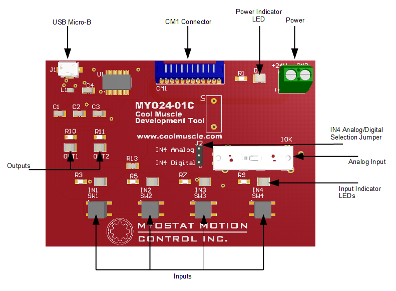
The MYO24 CM1 development tool is meant to be used as a simple and convenient method for testing programming and simulating inputs and outputs on the CM1 motor. The tool comes equipped with a USB converter for easy communications, four input buttons for simulating sensors and other inputs, a linear potentiometer for simulating an analog input, and two LEDs for showing the state of the motor outputs. The MYO24 connects to the motor easily using a 12-pin straight through cable.
The MYO24 is powered by the same 24VDC power supply as the motor and features a varistor on-board to help reduce or eliminate voltage spikes from the motor. Power is connected to the screw terminal on board and is transferred to the motor through the 12-pin connector. There is no need for a separate power supply or separate wiring for the motor power.
Connecting the MYO24
Power
The MYO24 is powered off of a 24VDC power supply and will pass power through to the connected motor. The components on the MYO24 are not powered from 24V but from the motor's 5VDC supply, so observe the maximum current draw for the motor you are using for proper power supply sizing.
Connect the output and ground from your power supply to the screw terminals labelled +24V and GND respectively.
It is recommended to not connect and/or disconnect the power connector, or the CM1 connector with power applied. Wait until all connections are made before powering up your power supply.
The Power indicator LED will light when the motor is powered up. This LED is powered from the motor, and not directly from the 24V power supply. This means there may be 24V on the MYO24 board, but the power indicator will not be lit if there is no motor connected, or if the motor is damaged or not functioning.
Communications
The MYO24 features a single USB Micro-B plug for connecting to your computer. Plug the cable from a USB plug on your computer to the USB Micro-B connector on the MYO24. The MYO24 should be automatically detected in windows and be assigned a COM port. If the drivers are not automatically installed, you can download the drivers here: http://www.ftdichip.com/Drivers/VCP.htm
In order to communicate to the CM1 motor, you will want to install Control Room.
Connection to CM1 Motor
The MYO24 connects to the CM1 motor through the 12-pin connector on the top of the board. See the drawing for the required CM1SRL1 cable below:
Inputs
The MYO24 features a tactile button for each input. Because Input 1 is used on the CM1 motor for communications, the IN1 button will only function if there is no USB cable connected to the MYO24 board.
Above each button is an LED. This LED will show that the input button is activated. This LED is not an indicator of anything from the motor, but merely that the button is depressed and is functioning. If the LED is lit, the motor should be getting the activation signal from that button.
Input 4 features a jumper pin to select either the tactile button, or a sliding potentiometer. This is used to simulate the analog input on the motor if needed. To select the potentiometer, set the jumper to IN4 Analog. To use the tactile button, set the jumper to IN4 Digital. The potentiometer will vary the voltage in to input 4 from 0 to 4.5V.
Outputs
The MYO24 features an LED for each of the two outputs on the CM1 motor. Because output 1 is used on the CM1 motor for communications, the OUT1 LED will only function if there is no USB cable connected to the MYO24 board.
Each LED will activate when the corresponding motor output is activated.
Overview
Content Tools