
MBT - Codesys Demo Application
Introduction
This Codesys demo application shows how to connect and control a CM1 MBT motor as a Modbus TCP Server (slave). This example can be extended to all IEC 61131 applications (Codesys, Schneider, Wago, Festo, TwinCAT, etc).
The application reads data from the motor using the Modbus 0x03 - Read Mulitple Registers function code, and writes using the 0x10 - Write Multiple Registers function code.
Codesys sets the address and function code separately. I.e. using the function code 0x03 and address 0x0000 instead of reading address 40001.
Application Setup
Devices View
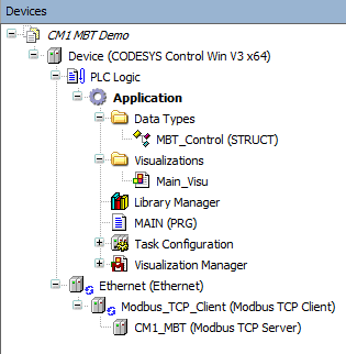
The Devices view shows the project layout. Importantly:
The Ethernet Device is added with the Modbus TCP Client attached. A Modbus TCP Server, the CM1 MBT, is then added to the client.
The MBT_Control user data type was created to simplify the modbus mapping. This is described further below.
Main_Visu - a small visualization simplifies user interaction
MAIN - the PLC logic
Modbus TCP Server Configuration and Mapping
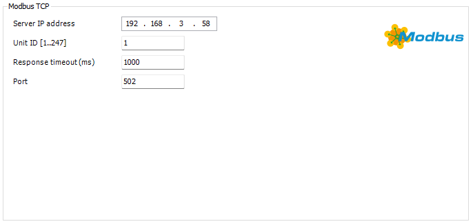
The Modbus TCP server has a few initial settings
IP Address → The assigned IP address of the CM1 MBT
Unit ID → Must be set to 1
Response Timeout → default is 1000 set as required
Port → Must be set to 502
Modbus TCP Server Settings
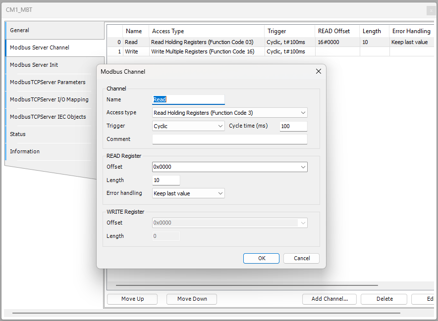
In the application two variants of converting the modbus 16-bit words to 32-bit integers is used. This is for demo purposes only. Either method can be used for both read and write data. The Modbus Server Channel is used to define the read and write registers.
Motor Status and Information Mapping
The following status and information variables are read from the motor from the following Modbus addresses.
Name | Description | Address - hex (decimal) |
|---|---|---|
Ex | Position Error | 0x0000 (0d) |
Px | Motor Actual Position | 0x0002 (2d) |
Sx | Actual Speed | 0x0004 (4d) |
Tx | Actual Torque | 0x0006 (6d) |
Ux | Motor Status (in position, error, running, etc) | 0x0008 (8d) |
The image below show Modbus channel 0 set to read multiple registers through function code 3. The starting address is 0x0000 with a length of 10.
Next the channel is mapped to the set of variables in MAIN.
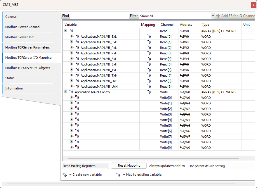
The variables are defined in MAIN as High and Low. They will be combined in logic as a single 32-bit integer (DINT).
	MB_ExH : WORD;
	MB_ExL : WORD;
	MB_PxH : WORD;
	MB_PxL : WORD;
	MB_SxH : WORD;
	MB_SxL : WORD;
	MB_TxH : WORD;
	MB_TxL : WORD;
	MB_UxH : WORD;
	MB_UxL : WORD;

    Ex: DINT;		//0x0000 (0d)- Position Error
	Px : DINT;		//0x0002 (2d) - Motor Position
	Sx : DINT;		//0x0004 (4d) - Motor Speed
	Tx : DINT;		//0x0006 (6d) - Motor Torque
	Ux: DINT;		//0x0008 (8d) - Motor Status
Motor Control Mapping
The following variables are written to the motor to control it.
Name | Description | Address - hex (decimal) |
|---|---|---|
P0 | Target Position | 0x002A (42d) |
S0 | Target Speed | 0x002C (44d) |
A0 | Target Acceleration | 0x002E (46d) |
V0 | N/A | 0x0030 (48d) |
R0 | Controlword | 0x0032 (50d) |
The image below show Modbus channel 1 set to writemultiple registers through function code 16. The starting address is 0x002A with a length of 10.
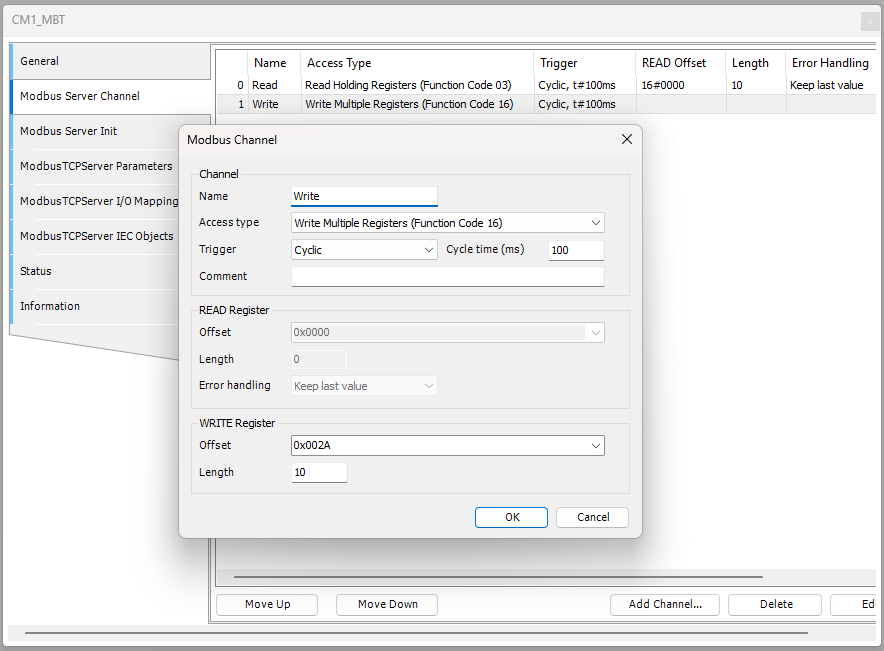
Next the channel is mapped to the Control variable in MAIN.
The MBT_Control struct is defined in the length and order or the modbus message
TYPE MBT_Control :
STRUCT
	P0 : DINT;		//0x002A (42d) - Target Position
	S0 : DINT;		//0x002C (44d) - Target Speed
	A0 : DINT;		//0x002E (46d) - Target Acceleration
	V0 : DINT;		//0x0030 (48d) - V0 not used
	R0 : DINT;		//0x0032 (50d) - Controlword
END_STRUCT
END_TYPE
This simplifies our mapping as the Modbus words are mapped directly into the variable structure.
Logic and Visualization
The following logic is set in MAIN
PROGRAM MAIN
VAR
	ExecuteStart : BOOL := FALSE;
	ExecuteStop : BOOL := FALSE;
	ExecuteEnable : BOOL := FALSE;
	ExecuteDisable : BOOL := FALSE;
	ExecuteHome : BOOL := FALSE;

	Control : MBT_Control;

	MB_ExH : WORD;
	MB_ExL : WORD;
	MB_PxH : WORD;
	MB_PxL : WORD;
	MB_SxH : WORD;
	MB_SxL : WORD;
	MB_TxH : WORD;
	MB_TxL : WORD;
	MB_UxH : WORD;
	MB_UxL : WORD;

	Ex: DINT;		//0x0000 (0d)- Position Error
	Px : DINT;		//0x0002 (2d) - Motor Position
	Sx : DINT;		//0x0004 (4d) - Motor Speed
	Tx : DINT;		//0x0006 (6d) - Motor Torque
	Ux: DINT;		//0x0008 (8d) - Motor Status
END_VAR//Read variables are an example of reading individually as words and converting to DINT
Ex := DWORD_TO_DINT(SHL(WORD_TO_DWORD(MB_ExH),16) OR WORD_TO_DWORD(MB_ExL));
Px := DWORD_TO_DINT(SHL(WORD_TO_DWORD(MB_PxH),16) OR WORD_TO_DWORD(MB_PxL));
Sx := DWORD_TO_DINT(SHL(WORD_TO_DWORD(MB_SxH),16) OR WORD_TO_DWORD(MB_SxL));
Tx := DWORD_TO_DINT(SHL(WORD_TO_DWORD(MB_TxH),16) OR WORD_TO_DWORD(MB_TxL));
Ux := DWORD_TO_DINT(SHL(WORD_TO_DWORD(MB_UxH),16) OR WORD_TO_DWORD(MB_UxL));
//Write variables and an example of being placed together in a data type (MBT_Control) and then written as one in the modbus server
//The R0 (controlword) is set from the push bottons in the visualization
//See https://docs.myostat.ca/cm1-c/user-guide/running-the-motor-in-modbus-mode#RunningthemotorinModbusMode-ControlWord
(*
0 --> Do nothing
1 --> Start the position move
2 --> Stop the motor
3 --> Enable the motor
4 --> Disable the motor
5 --> Home the motor
*)
IF (ExecuteStart) THEN Control.R0 := 1;
ELSIF (ExecuteStop) THEN Control.R0 := 2;
ELSIF (ExecuteEnable) THEN Control.R0 := 3;
ELSIF (ExecuteDisable) THEN Control.R0 := 4;
ELSIF (ExecuteHome) THEN Control.R0 := 5;
ELSE
Control.R0 := 0;
END_IFAs seen the logic converts the read high and low words into the signed integer variable. This is an extra step compared to the write variables. It does give the ability to switch the high and low words if required.
The controlword R0 is then set depending on the state or the control button.
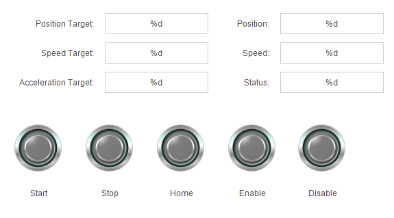
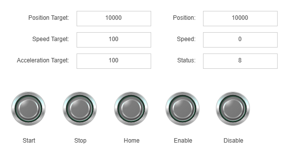
The visualization controls are mapped to the variables in MAIN.
The project can now be run. A speed, acceleration and target position are required to execute a move.
Codesys Project File
The project is available for download as a project archive. It was created with Codesys V3.5 SP21 Patch 4 + (64-bit). It is recommended to open it using File → Project Archive → Extract Archive…