...
- Connecting a digital input to GND will produce a logical high on the device.
- All digital inputs can be monitored by the EtherCAT master.
- Inputs 2 and 3 are also connected to the motor controller. This allows them to function as inputs for embedded home routines as well as any standard CML programming when in CML mode
- The analog input is referenced by the motor and available in CML mode
- Output 1 is controller by the EtherCAT slave controller. It is switched on and off by the EtherCAT master
- Output 2 can be programmed as a standard motor output and cannot be controller directly by the EtherCAT master.
| Section |
|---|
| Column |
|---|
| 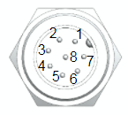 Image Added Image Added
|
| Column |
|---|
| Connector | Part Number | Supplier |
|---|
| Motor connector | 09 0481 22 08
| Binder | | Female cable side mating connector | 99 0480 102 08 | Binder | | 4m I/O cable | CM1M9-8F-4000 | Myostat |
|
|
| Section |
|---|
| Column |
|---|
|
Image Removed |
| Column |
|---|
|
| Pin # | Name | EtherCAT Function | Motor Function | Specifications |
|---|
| 1 - orange | IN1 | Digital input 1 | - |
| Parameter | Min | Max | Unit |
|---|
| Voltage Range | 0 | 36 | V | | Low Level | 0 | 1.4V | V | | High Level | 1.4 | 36 | V | | Continuous Current | - | 30 | mA | | Peak Current | - | 0.5 | A | | Pulse Width | - |
|
...
|
| 2 - brown | IN2 | Digital input 2 | Digital input 2 |
...
| 3 - green | IN3 | Digital input 3 | Digital input 3 |
...
| 4 - yellow | IN4 | Digital input 4 | - |
...
|
| 5 - purple | A-IN5 | - | Analog input 4 | 0-5V (10 bit resolution) |
| 6 - blue | OUT1 | Digital output 1 | - | 1A, NPN (sinking), 24V inductive load capable |
| 7 - black | OUT2 | - | Output 2 | 1A, NPN (sinking), 24V inductive load capable |
| 8 - red | GND | GND | GND | GND |
Colours indicated are for the standard CM1M9-8F-4000 I/O cable
USB Connection
The USB connector is a standard micro USB and is used to update the EtherCAT firmware. When it is plugged into a computer it will create a virtual serial port.
...