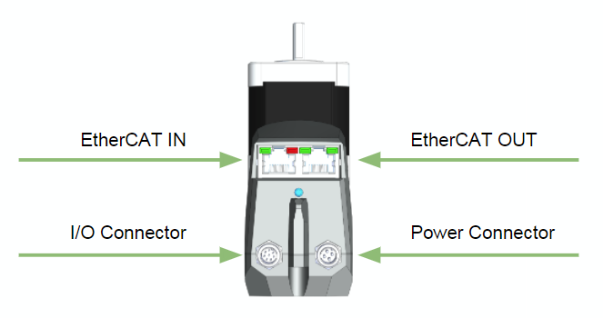
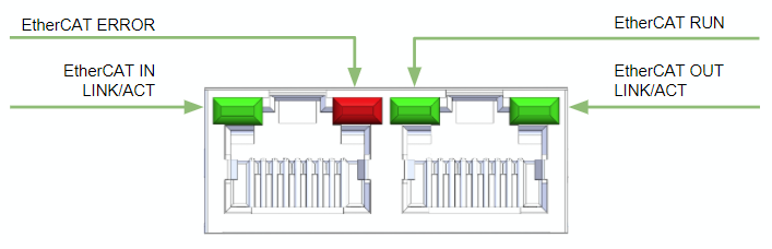
The following diagram shows an overview of all connectors and LEDs.
Wiring and LED Information (Copy)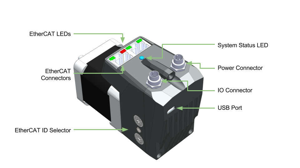 Image Added
Figure: Overview of Connections and status LEDs
| Anchor |
|---|
| Motor Connections |
|---|
| Motor Connections |
|---|
|
| Section |
|---|
| Column |
|---|
| 
|
|
| Section |
|---|
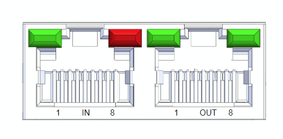
The EtherCAT IN and OUT ports use standard Ethernet RJ45 CAT5e connectors.
| Column |
|---|
| 
|
| Column |
|---|
| Pin # | Function |
|---|
| 1 | TX+ | | 2 | TX- | | 3 | RX+ | | 4 | GND | | 5 | GND | | 6 | RX- | | 7 | GND | | 8 | GND |
|
|
The power connector supplies 24V to the EtherCAT slave and the motor separately. These two can be tied together so both are off the same power supply.
...
- REVC Hardware
- Maintaining EtherCAT power and dropping motor power will not retain motor position as the the current position is evaluated on the motor controller.
- REVD Hardware
- Maintaining EtherCAT power and dropping motor power will
- retain motor position
- remove any ability for the motor to be driven (as power to the motor drive has been removed).
- Connecting a digital input to GND will produce a logical high on the device.
- All digital inputs can be monitored by the EtherCAT master.
- Inputs 2 and 3 are also connected to the motor controller. This allows them to function as inputs for embedded home routines as well as any standard CML programming when in CML mode
- The analog input is referenced by the motor and available in CML mode
- Output 1 is controller by the EtherCAT slave controller. It is switched on and off by the EtherCAT master
- Output 2 can be programmed as a standard motor output and cannot be controller directly by the EtherCAT master.
...
| Section |
|---|
| Column |
|---|
| 
|
| Column |
|---|
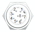
| Pin # | Name | EtherCAT Function | Motor Function | Specifications |
|---|
| 1 | IN1 | Digital input 1 | - | GND triggered, 24V tolerant | | 2 | IN2 | Digital input 2 | Digital input 2 | GND triggered, 24V tolerant | | 3 | IN3 | Digital input 3 | Digital input 3 | GND triggered, 24V tolerant | | 4 | IN4 | Digital input 4 | - | GND triggered, 24V tolerant | | 5 | IN5 | - | Analog input 4 | 0-5V (10 bit resolution) | | 6 | OUT1 | Digital output 1 | - | 1A, NPN (sinking), 24V inductive load capable | | 7 | OUT2 | - | Output 2 | 1A, NPN (sinking), 24V inductive load capable | | 8 | GND | GND | GND | GND |
|
|
The USB connector is a standard micro USB and is used to update the EtherCAT firmware. When it is plugged into a computer it will create a virtual serial port.
LEDs
EtherCAT Status LEDs
An EtherCAT slave device is required to have LEDs indicating different states.
| Section |
|---|
| Column |
|---|
| 
|
|
There is a Link/Activity LED for both the IN and OUT EtherCAT ports. The table below describes the indicator conditions and their associated states
| Link | Activity | Condition | Link/Activity Code |
|---|
| Yes | No | Port Open | On |
| Yes | Yes | Port Open | Flickering |
| No | N/A | Port Closed | Off |
The Run indicator shows the state of the EtherCAT State Machine. The indicator states are described in the table below.
| Indicator State | Slave State | Description |
|---|
| Off | Initialisation | The device is in state "Init" |
| Blinking | Pre-Operational | The device is in state "Pre-Operational" |
| Single Flash | Safe-Operational | The device is in state "Safe-Operational" |
| On | Operational | The device is in state "Operational" |
| Flickering | Init or Bootstrap | The device is booting and has not yet entered the "Init" state or,
the device is in state "Bootstrap. Firmware download is in progress. |
The Error indicator shall show device and EtherCAT errors. Errors are as defined in the table below.
...
| Error State | Error Name | Description | Example |
|---|
| On | Application controller
failure | A critial communication or application error has occured | - Over torque error
- Motor communication error
|
| Double flash | Process Data Watchdog timeout/
EtherCAT watchdog timeout | An application watchdog timeout has occured | Sync Manager watchdog timeout |
| Single flash | Local Error | Slave device application has changed the EtherCAT state autonomously, due to local error. | Device has changed from Op to safe-op due to EtherCAT error |
| Blinking | Invalid Configuration | General Configuration error |
|
| Flickering | Booting Error | Init state reached but boot error detected | Application boot error |
| Off | No Error | Device is in working condition |
|
| Anchor |
|---|
| System and Motor Status LED |
|---|
| System and Motor Status LED |
|---|
|
The system status LED provides feedback to the user on overall system status. The following states exist
...