Page History
...
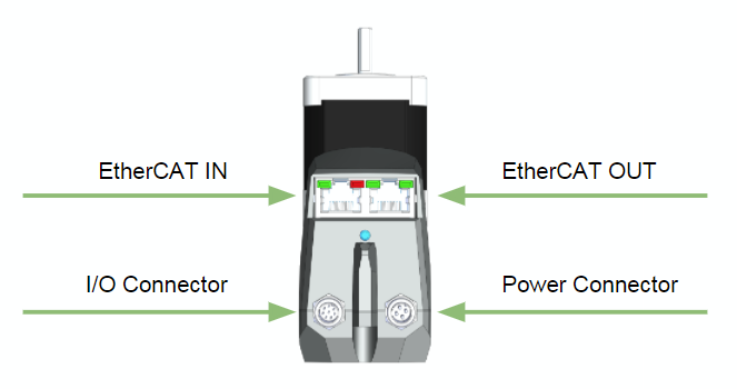
The following diagram shows an overview of all connectors and LEDs.
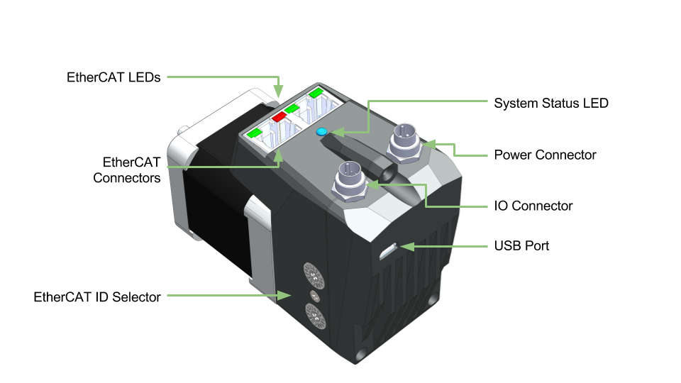
Figure: Overview of Connections and status LEDs
...
| Section | |||||||||
|---|---|---|---|---|---|---|---|---|---|
|
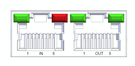
EtherCAT Connectors
...
The EtherCAT
...
ports use standard Ethernet RJ45 CAT5e, M8-A or M8-D connectors depending on the motor variant. They are labeled IN and OUT as per the EtherCAT standard.
...
Connector Options
RJ45
- Amphenol - RJHSE538B02
M8-A Female
- TE Connectivity - T4041017041-000
- M8-D Female
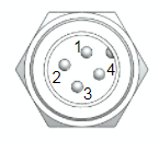
Pinout
| RJ45(1) | M8-A | M8-D | |
|---|---|---|---|
Tx+ | 1 | 1 | 1 |
| Rx+ | 3 | 2 | 2 |
| Rx- | 6 | 3 | 4 |
| Tx- | 2 | 4 | 3 |
(1) Pins 4,5,7 and 8 are connected to GND.
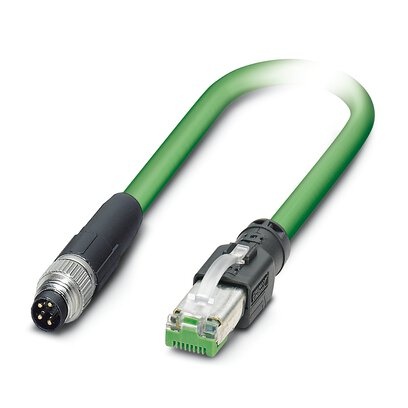
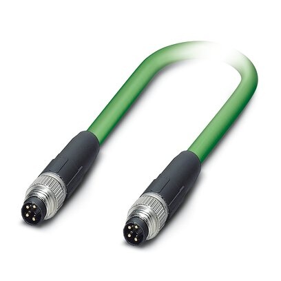
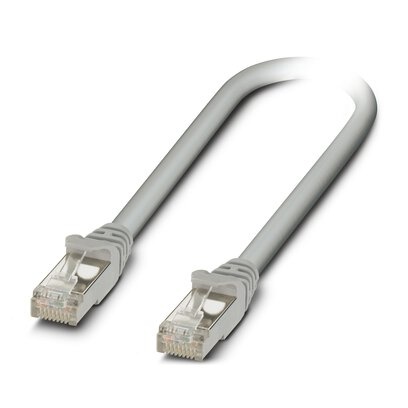
Example Cables
All ethernet cables are standard pinouts and are available from a variety of online suppliers or cable houses. Here are a few example cables from the Phoenix Contact NBC series
| Image | Part Number | Description | Digikey Link |
|---|---|---|---|
| 1407353 | M8-A male to RJ45 | Digikey - 1407353 |
| 1407349 | M8-A male to M8A male | Digikey - 1407349 |
| 1227562 | RJ45 to RJ45 | Digikey - 1227562 |
| Column | ||
|---|---|---|
| ||
|
...
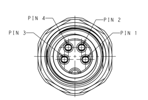
Power Connector
The power connector supplies 24V to the EtherCAT slave and the motor separately. These two can be tied together so both are off the same power supply.
...
| Connector | Part Number | Supplier |
|---|---|---|
| Motor connector | 09 0081 20 04 | Binder |
| Female cable side mating connector | 99 0080 102 04 | Binder |
| 4m power cable | CM1M9-4F-4000 | Myostat |
- The CM1M9-4F-4000 is 24AWG with conductor resistance of 97.5Ω/km
- The HF version with EXT-3D cable has a resistance of 91.1Ω/km
| Section | |||||||||||||||||||||||||||||
|---|---|---|---|---|---|---|---|---|---|---|---|---|---|---|---|---|---|---|---|---|---|---|---|---|---|---|---|---|---|
|
Colors indicated are for the standard CM1M9-4F-4000 power cable.
- NOTE: There is no reverse polarity protection. Ensure the 24V power is connected correctly before powering the unit.
- REVC Hardware
- Maintaining EtherCAT power and dropping motor power will not retain motor position as the the current position is evaluated on the motor controller.
- REVD Hardware
- Maintaining EtherCAT power and dropping switching off motor drive power will
- retain motor position
- remove any ability for the motor to be driven (as power to the motor drive has been removed).
I/O Connector
- Connecting a digital input to GND will produce a logical high on the device.
- All digital inputs can be monitored by the EtherCAT master.
- Inputs 2 and 3 are also connected to the motor controller. This allows them to function as inputs for embedded home routines as well as any standard CML programming when in CML mode
- The analog input is referenced by the motor and available in CML mode
- Output 1 is controller by the EtherCAT slave controller. It is switched on and off by the EtherCAT master
- Output 2 can be programmed as a standard motor output and cannot be controller directly by the EtherCAT master.
...
| Section | |||||||||||||||||||
|---|---|---|---|---|---|---|---|---|---|---|---|---|---|---|---|---|---|---|---|
|
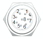
| Pin # | Name | EtherCAT Function | Motor Function | Specifications | |||||||
|---|---|---|---|---|---|---|---|---|---|---|---|
| Digital Inputs - Sourcing (supply 0V to trigger) | Parameter | Min | Max | Unit | |||||||
1 - orange 2 - brown 3 - green 4 - yellow | IN1 IN2 IN3 IN4 | Digital input 1 Digital input 2 Digital input 3 Digital input 4 | - | ||||||||
| Parameter | Min | Max | Unit | Digital input 2 Digital input 3 - | Voltage Range | 0 | 36 | V | |||
| Input ON level | 0 | 1. | 4V4 | V | High Level|||||||
| Input OFF level | 1.4 | 36 | V | ||||||||
| Continuous Current | - | 30 | mA | ||||||||
| Peak Current | - | 0.5 | A | ||||||||
| Pulse Width | - | 1 | ms | ||||||||
| 2 - brown | IN2 | Digital input 2 | Digital input 2 | ||||||||
| 3 - green | IN3 | Digital input 3 | Digital input 3 | ||||||||
| 4 - yellow | IN4 | Digital input 4 | - | ||||||||
| Analog Input (0-5V) | Parameter | Min | Max | Unit | |||||||
| 5 - purple | A-IN5 | - | Analog input 4 | Parameter | Min | Max | UnitVoltage Range | 0 | 5 | V | |
| Resolution | 10 bit | ||||||||||
| Digital Outputs - Sinking (output supplies 0V when asserted) | Parameter | Min | Max | Unit | |||||||
6 - blue 7 - black | OUT1 OUT2 | Digital output 1 - | Parameter | Min | Max | Unit- Output 2 | Voltage Range | 0 | - | V | |
| Continuous Current | - | 1 | A | ||||||||
Inductive Load Peak | rev currentRev Current | - | 0.2 | A | |||||||
Inductive Load Peak | Rec Volt.Rev Voltage | - | 70 | V | 7 - black | OUT2 | - | ||||
| Signal Ground (0V) | Parameter | Min | Max | Unit | Output 2|||||||
| 8 - red | GND | GND | GND | GND | |||||||
...
| 0V | 0V | 0V | Voltage Range | 0 | 0 | V |
- Colors indicated are for the
...
- standard CM1M9-8F-4000
...
- I/O cable.
- For custom cable length pin-out and colors see CM1M9-8F.PDF
USB Connection
The USB connector is a standard micro USB and is used to update the EtherCAT firmware. When it is plugged into a computer it will create a virtual serial port.
...
| Section | |||||||||||||||||||||||||||||
|---|---|---|---|---|---|---|---|---|---|---|---|---|---|---|---|---|---|---|---|---|---|---|---|---|---|---|---|---|---|
|
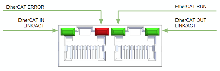
Link/Activity Indicator
...
The system status LED provides feedback to the user on overall system status. The following states exist
| LED Colour | Description | ||
|---|---|---|---|
| Red | Motor Error Solid:
Blinking
Flashing:
| ||
| Green | Solid - CiA402 | ModeBlue | Solid - CMLMode |
Overview
Content Tools